


Machine and Implement Setup
Continuedon next page JS56696,00009D61911MAY113/4
PC9902—UN—09JAN07
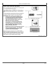
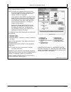
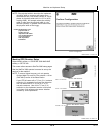
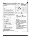
Track Spacing
PC9903—UN—09JAN07
Track Spacing
A—m (ft)/(rows) button
B—Implement Width
C—Track Spacing
D—Physical Width
E—Row Width
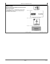
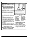
Implement Widths—Used to enter implement width
and track spacing for guidance. This value is also used
to calculate total area when documenting the operation.
Verify implement type, model, name, implement width and
track spacing when changing implements. Implement
width and track spacing are independent of each other.
NOTE: IMPLEMENT tab will show HEADER for
Combines, ROW UNITS for Cotton Pickers,
and BOOM for Sprayer.
Implement width may come from controller on
select controllers such as SeedStar.
In some cases, a higher degree of precision can be
achieved for track spacing when track spacing is
entered in by rows instead of feet. More decimal
places are used in the track spacing calculation
when entered in by rows versus the three decimal
places allowed when entered by feet.
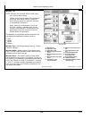
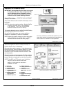
Defining Implement Width and Track Spacing.
Implement width and track spacing can be defined two
ways: enter the working width of the implement, or enter
the number of rows and the row spacing. To toggle
between these two, select the m (ft)/(rows) button.
•
Implement Width m (ft)—enter total implement working
width
•
Implement Width rows—enter number of rows and the
row spacing in inches
Track Spacing—Used in guidance for how far each pass
is from the last pass. It is entered the same way as
Implement Width. For “perfect” guess rows, this distance
will be the same as Implement Width. To ensure some
overlap for tillage or spraying, or to account for some
GPS drift, you may choose to make the Track Spacing
somewhat less than the Implement Width.
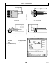
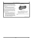
Physical Width—The actual width of the entire implement
when being used in the field when the implement is raised.
It is sometimes larger than Implement Width.
Using a planter as an example, the marker arms and
blades are wider than the working width. This width
needs to be entered if markers are not used, or are used
and completely folded on the ends. If markers are only
partially folded during turns, enter this larger dimension.
IMPORTANT: Width measurements are used to help
alert an operator of potential intersections
between the implement and an impassable
boundary. The operator still needs to be aware
of potential collisions if there are times the
implement is wider than the dimension entered
(e.g. marker arm lowered). If markers are used
in the field, add the width of both markers to
give ultimate alarms of possible intersections.
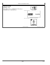
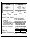
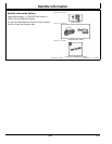
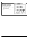
NOTE: As a buffer to avoid obstacles, additional Physical
Width may beadded to the implement to compensate
for several things, one of these being GPS drift.
Signal
Approximate Physical Width
added to Implement
RTK
0.6 m (2 ft)
SF2 0.9 m (3 ft)
SF1 3.4 m (11 ft)
Physical Width Table
1510
061611
PN=18