


Instrument Panel - Elect. Cont. Later Engines
OURGP11,0000074 –19–27JUL06–1/1
Using Diagnostic Gauge to Access Engine
Information
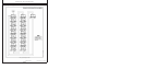
RG13132 –UN–09SEP03
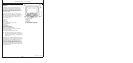
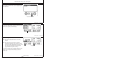
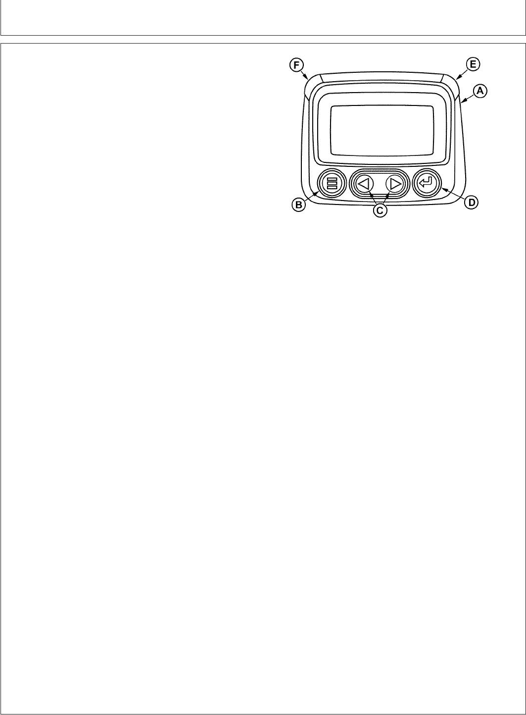
Diagnostic Gauge (Later Engines)
A—Diagnostic Gauge
B—Menu Key
C—Arrow Keys
D—Enter Key
E—Red “STOP ENGINE” Indicator Light
F—Amber “WARNING” Indicator Light
The diagnostic gauge (A) allows the operator to view
many readouts of engine functions and trouble codes
(DTCs). The gauge is linked to the electronic control
system and its sensors. This allows the operator to
monitor engine functions and to troubleshoot the engine
systems when needed.
Press the menu key (B) to access the various engine
functions in sequence. The displays can be selected as
either customary English or metric units. The following
menu of engine parameters can be displayed on the
diagnostic gauge window:
• Engine hours
• Engine rpm
• System voltage
• Percent engine load at the current rpm
• Coolant temperature
• Oil pressure
• Throttle position
• Intake manifold temperature
• Current fuel consumption
• Active service (diagnostic) codes
• Stored service (diagnostic) codes from the engine
• Set the units for display
• View the engine configuration parameters
NOTE: Engine parameters which can be accessed will
vary with the engine application. Six languages for
readouts are available and can be selected during
setup of gauge.
The diagnostic gauge includes a graphical backlit Liquid
Crystal Display (LCD) screen. The display can show either
a single parameter or a quadrant display showing four
parameters simultaneously. The diagnostic gauge uses
two arrow keys (C) for scrolling through the engine
parameter list and viewing the menu list and an enter key
(D) for selecting highlighted items. The red (E) and amber
(F) lights are used to signal active trouble code received
by the diagnostic gauge.
17-4
080706
PN=67