


Instrument Panel - Elect. Cont. Later Engines
OURGP11,0000073 –19–04AUG06–2/3
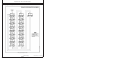
Instrument Panel (Continued)
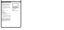
A—Diagnostic Gauge/Hour Meter
The diagnostic gauge (A) displays diagnostic trouble
codes (DTCs) as they are accessed. Other information
on the engine can be accessed using the touch keys
(N, O and P). The hour meter feature shows the
operating hours of the engine and should be used as a
guide for scheduling periodic maintenance. If the
diagnostic gauge receives a trouble code from an
engine control unit, the current display will switch to a
warning or shutdown (depending on the severity of the
code) screen that will display the trouble code number,
the description of the code and the corrective action
needed.
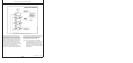
B—Tachometer
The tachometer (B) indicates engine speed in
hundreds of revolutions per minute (rpm).
C—Voltmeter (Optional)
The voltmeter (C) indicates system battery voltage.
The amber “Warning” light (Q) will illuminate when
battery voltage is too low for proper operation of the
fuel injection system.
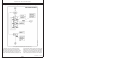
D—Audible Alarm (Optional)
The audible alarm (D) will sound whenever low oil
pressure, high coolant temperature, or water-in-fuel
conditions exist. This includes all signals that light up
the amber “warning” indicator (intermittent alarm) or
the red “stop engine” indicator (steady alarm).
E—Audible Alarm Override Button
The optional audible alarm has an override button (E)
that silences the audible alarm for approximately two
minutes when pressed.
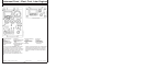
F—Key Start Switch
The three-position key start switch (F) controls the
engine electrical system. When the key switch is
turned clockwise to “START”, the engine will crank.
When the engine starts, the key is released and
returns to the “ON” (RUN) position.
G—Override Shutdown Rocker Switch
Switch will be present, but may not be active,
depending on engine controller (ECU) options
originally selected. If switch is active, pressing the
upper half of the override shutdown switch (G) will
override an engine shutdown signal. The switch must
be pressed within 30 seconds to prevent undesired
shutdown of engine. Pressing this switch will override
the engine shutdown for 30 seconds at a time to move
vehicle to a safe location.
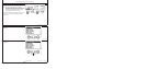
H—Bump Speed Enable Rocker Switch
This is a three-position switch (H) with the center
position as “OFF” (locked). With this switch in the
“OFF” position, the speed select switch (I) is also
locked, to prevent accidental changes in operating
speed. Pressing upper or lower half of switch (H) will
unlock or enable the bump speed switch to take effect
using speed select switch (I).
I—Speed Select Rocker Switch
The speed select switch (I) is used to bump engine
speed up (+) or down (-) in small increments during
operation. This switch must be used with the bump
speed enable switch (H) in the unlocked position (top
or bottom half of button depressed).
J—High-Low Speed Select Rocker Switch
The high-low speed select switch (J) is used to set the
engine operating speeds at slow (turtle) or fast (rabbit).
Factory preset idle speeds can also be adjusted using
bump speed enable switch (H) with speed select
switch (I).
The basic instrument panel will have the high-low
speed select switch only. Press and hold up (+) or
down (-) to adjust engine speed as desired. The
engine speed selected will not be held in the memory.
To adjust engine speeds, See Changing Engine
Speeds in Section 18.
17-2
080706
PN=65
Continued on next page