


Troubleshooting
OURGP11,0000272 –19–27JUL06–1/1
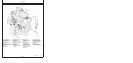
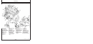
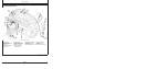
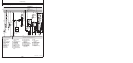
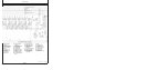
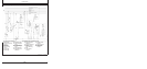
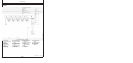
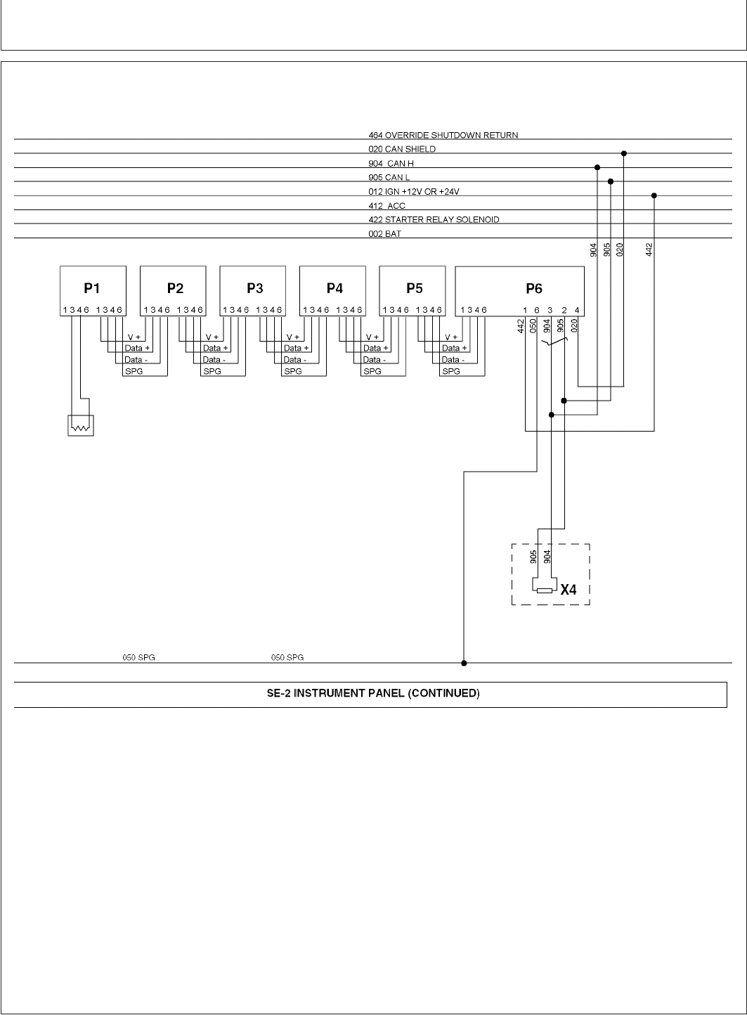
Engine Wiring Diagram (With Later Full-Featured Electronic Instrument Panel)—
Continued
RG13272 –UN–26JAN04
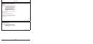
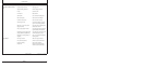
B1—Analog Throttle P3—Oil Pressure Gauge S3—Bump Enable Switch X2—Alternator Harness
F1—Fuse (30 Amp) (Harness) P4—Coolant Temperature (Momentary) Connector
G1—Alternator Gauge S4—High-Low Speed Select X3—Single Point Ground
K1—Starter Relay P5—Tachometer Display Switch X4—CAN Terminator
M1—Starter Motor P6—Hour Meter/Diagnostic S5—Override Shutdown X5—Analog Throttle
N1—Transient Voltage Gauge Switch (Momentary) Connector
Protector S1—Ignition Key Switch V1—Diode
P1—Optional Gauge S2—Speed Select Switch X1—Vehicle Harness
P2—Optional Gauge (Momentary) Connector
45-9
080706
PN=203