


Service as Required
OURGP11,000013C –19–27JUL06–1/1
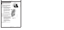
Checking Fuses
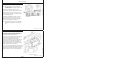
RG11938 –UN–06NOV01
Early Engines with Electronic Instrument Panel
A—5 Amp Fuse
NOTE: The instrument panels for later electronically
controlled engines as described in Section 17 do
not have this fuse.
Check fuse (A) located in fuse holder on face of
instrument panel. If defective, replace with a 5-amp fuse.
A separate wiring harness fuse (10 amp) and a main
system fuse (20 amp) are shown in the Wiring Diagrams
in the Troubleshooting Section.
On 4045HF475 and 6068HF475 engines, a separate
wiring harness for glow plugs (not shown) has fuse
protection. To replace fuse, remove cap from holder on
jumper cable and replace with a 50-amp fuse.
NOTE: On 4045DF/TF 270 engines, refer to supplier’s
instructions and diagrams for fuse location and
type.
OURGP12,00001E0 –19–27JUL06–1/1
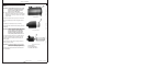
Checking Air Compressors (If Equipped)
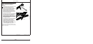
RG12836 –UN–27FEB03
Air Compressor (Optional)
Air compressors are offered as options with John Deere
OEM engines to provide compressed air to operate
air-powered devices like vehicle air brakes.
Air compressors are engine-driven piston types. They are
either air cooled or cooled with engine coolant. The
compressors are lubricated with engine oil. The
compressor runs continuously as gear or spline driven by
the auxiliary drive of the engine but has “loaded” and
“unloaded” operating modes. This is controlled by the
vehicle’s air system (refer to vehicle technical manual for
complete air system checks and services).
See your John Deere engine distributor or servicing dealer
for diagnostic and troubleshooting information. If diagnosis
leads to an internal fault in the compressor, replace the
complete compressor as a new or remanufactured unit.
40-11
080706
PN=184