


Troubleshooting
OURGP11,0000277 –19–27JUL06–1/1
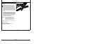
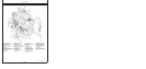
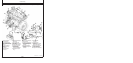
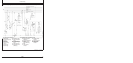
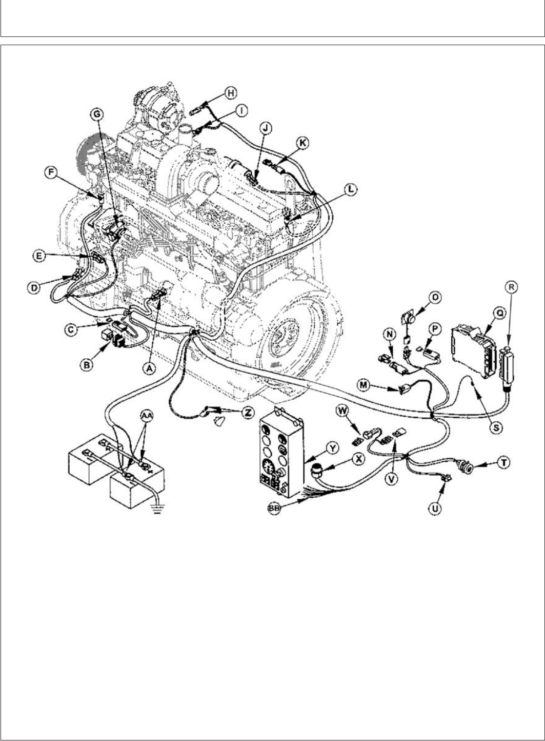
Engine Wiring Layout (Electronic Fuel System With Bosch VP44 Injection Pump)
RG11939A –UN–05JUN02
A—Oil Pressure Sensor I—Manifold Air Temperature Q—Engine Control Unit (ECU) W—Remote ON/OFF
B—Fuel Pump Relay (MAT) Sensor R—ECU Connector Connector
C—Fuel Pump Relay Fuse J—Fuel Transfer Pump S—System Ground (ECU must X—Instrument Panel
D—Crankshaft Position Sensor K—Fuel Heater also be grounded to frame) Connector
E—Fuel Injection Pump Event L—Fuel Temperature Sensor T—CAN Network Diagnostic Y—Optional Instrument Panel
Sensor M—Network CAN Connector Connector (Earlier Version Shown)
F—Coolant Temperature N—Isochronous Governor U—Blink-Code Diagnostic Z—Starter Relay Connections
Sensor Select Connector Connector AA—Power and Ground
G—Fuel Injection Pump O—Transient Voltage V—Secondary Analog Throttle Battery Connections
Connector Protection (TVP) Module Connector BB—Optional Wire Extensions
H—Alternator Ignition P—Main System Fuse (20
Connector Amp)
45-4
080706
PN=198