


Instrument Panel - Elect. Cont. Earlier Engines
OURGP11,000027A –19–07AUG06–2/7
RG11169 –UN–01NOV00
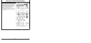
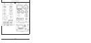
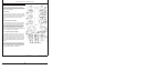
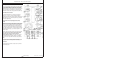
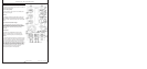
Instrument Panel
IMPORTANT: Any time an electric gauge or meter
does not register correctly, replace with
a new one. Do not attempt to repair it.
All gauges are plug-in type.
Following is a brief description of the electronic controls
found on John Deere-provided instrument panels. Refer to
manufacturer’s literature for information on controls not
provided by Deere.
Engine Oil Pressure Gauge
The engine oil pressure gauge (A) indicates engine oil
pressure in pounds per square inch (psi) or kPa. An
optional audible alarm (G) warns the operator if engine oil
pressure falls below a safe operating pressure.
Amber “Warning” Indicator
The amber “WARNING” indicator (B) signals an abnormal
condition such as low oil pressure, high coolant
temperature, water in fuel, low battery voltage, etc.
Observe displayed code in window of diagnostic
gauge/hour meter (D) for diagnostic trouble code (DTC).
(Use the service code menu. See USING DIAGNOSTIC
GAUGE TO ACCESS ENGINE INFORMATION later in
this section.)
Red “Stop Engine” Indicator
The Red “STOP ENGINE” indicator (C) signals operator to
stop engine immediately or as soon as safely possible. A
condition exists that could cause damage to engine.
Diagnostic Gauge/Hour Meter
The diagnostic gauge/hour meter (D) displays diagnostic
trouble codes (DTCs) as they are accessed. Other
information on the engine can be accessed using the
touch switches (E and F). The hour meter shows the
operating hours of the engine. If engine trouble occurs,
the gauge will alternately flash from displayed parameter
to the message “SvrcCode”. Then the touch switches (E
and F) can be used to access the trouble code (see
following).
16-2
080706
PN=48
Continued on next page