


Troubleshooting
OUOD007,0000036 –19–27JUL06–1/1
Intermittent Fault Diagnostics (With Electronic Controls)
Intermittent faults are problems that periodically “go
away”. A problem such as a terminal that intermittently
doesn’t make contact can cause an intermittent fault.
Other intermittent may be set only under certain
operating conditions such as heavy load, extended
idle, etc. When diagnosing intermittent faults, take
special note of the condition of wiring and connectors,
since a high percentage of intermittent problems
originate here. Check for loose, dirty or disconnected
connectors. Inspect the wiring routing, looking for
possible shorts caused by contact with external parts
(for example, rubbing against sharp sheet metal
edges). Inspect the connector vicinity, looking for wires
that have pulled out of connectors, poorly positioned
terminals, damaged connectors and corroded or
damaged splices and terminals. Look for broken wires,
damaged splices, and wire-to-wire shorts. Use good
judgement if component replacement is thought to be
required.
NOTE: The engine control unit (ECU) is the
component LEAST likely to fail.
Suggestions for diagnosing intermittent faults:
• If the problem is intermittent, try to reproduce the
operating conditions that were present when the
diagnostic trouble code (DTC) set.
• If a faulty connection or wire is suspected to be the
cause of the intermittent problem: clear DTCs, then
check the connection or wire by wiggling it while
watching the diagnostic gauge to see if the fault
resets.
Possible causes of intermittent faults:
• Faulty connection between sensor or actuator
harness.
• Faulty contact between terminals in connector.
• Faulty terminal/wire connection.
• Electromagnetic interference (EMI) from an
improperly installed 2-way radio, etc., can cause
faulty signals to be sent to the ECU.
NOTE: Refer to wiring diagrams earlier in this section
as a guide to connection and wiring.
OURGP11,000012B –19–27JUL06–1/4
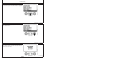
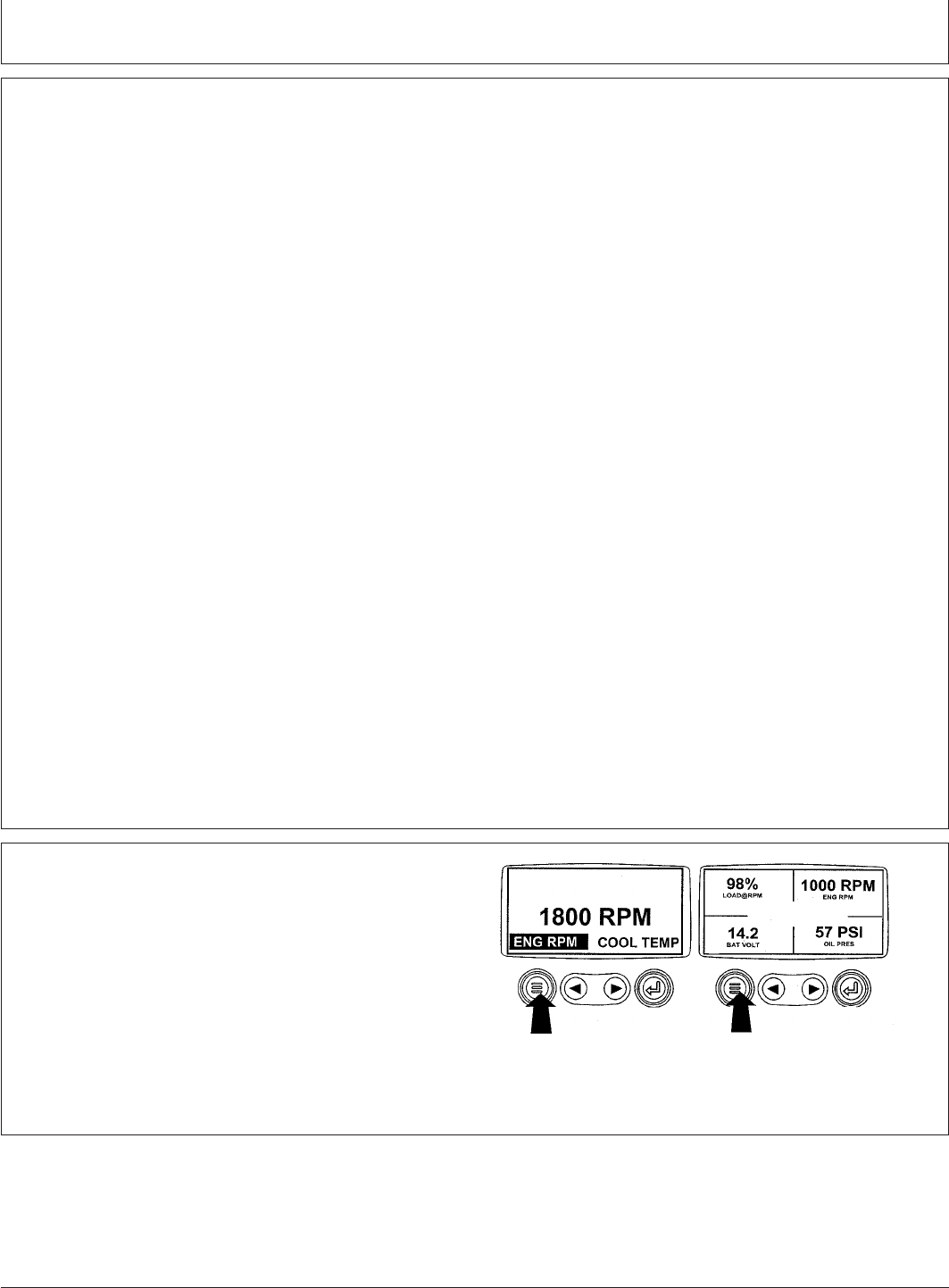
Displaying Diagnostic Gauge Software (Later
Engines)
RG13159 –UN–26SEP03
Menu Key
NOTE: The following steps can be used to display the
software version of the diagnostic gauge if needed
by your dealer for troubleshooting. This is a read
only function.
1. Starting at the single or four engine parameter display,
press the "Menu" key.
Continued on next page
45-29
080706
PN=223