Page 47
SSeeccttiioonn 77
DDIIAAGGNNOOSSTTIICC TTEESSTTSS
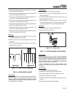
3. In Step 7, if Wire 0 reads “Continuity”, but resistor does not
measure 1 ohm, replace the Battery Charge Resistor.
4. If all of the Steps in this test pass, perform “Insulation
Resistance Test” on page 13.
TEST 18 - TRY CRANKING THE ENGINE
DISCUSSION:
If the Fuel Primer Switch on the generator panel is
actuated, but the Fuel Pump does not run (priming
function doesn't work), perhaps battery voltage is not
available.
PROCEDURE:
Hold the Start-Stop Switch at “START”. The engine
should crank and start.
RESULTS:
1. If the engine cranks normally, but the priming function still
doesn't work, go to Test 19.
2. If engine will not crank, go to Test 21. Refer to Problem 6 of
Section 6.
3. If engine cranks but won't start, go to Problem 7 of Section 6.
4. If engine starts hard and runs rough, go to Problem 8 of
Section 6.
TEST 19- TEST PRIMER SWITCH
DISCUSSION:
A defective primer switch can prevent the priming
function from occurring.
Switch failure can also prevent the engine from start-
ing, since the switch is in series with the Wire14 circuit.
(Also see “Fuel Primer Switch,” page 25).
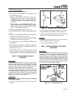
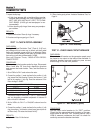
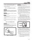
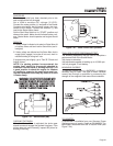
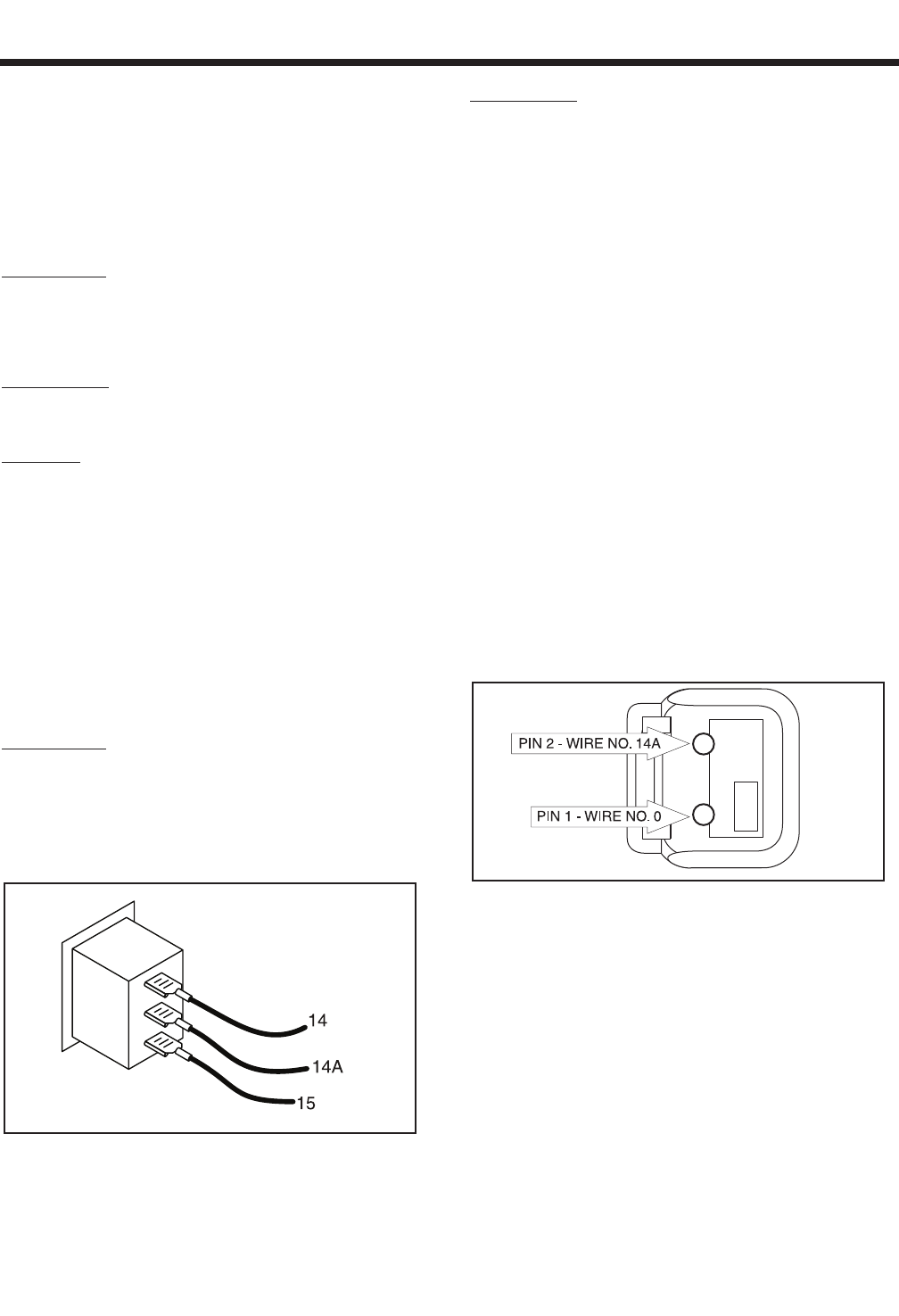
Figure 7-11. – Primer Switch
PROCEDURE:
1. Set a VOM to read battery voltage (12 VDC).
2. Connect the positive (+) meter test lead to the Wire 15 terminal
of the Primer Switch (leave Wire 15 connected to the switch).
Connect the negative (-) meter test lead to frame ground. The
meter should indicate battery voltage.
3. Connect the positive (+) meter test lead to the Wire 14 terminal
of the Primer Switch (leave Wire 14 connected to the switch).
Connect the negative (-) meter test lead to a clean frame
ground. Set the Start-Stop switch to “START”. The engine
should crank and battery voltage should be measured.
4. Connect the positive (+) meter test lead to the Wire 14A termi-
nal of the Primer Switch, the negative (-) meter test lead to
frame ground.
a. With the Primer Switch NOT actuated, no
voltage should be indicated.
b. Actuate the switch to its “PRIME” position
and the meter should read battery voltage.
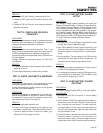
5. For gasoline models, disconnect Connector 2 at the Fuel
Pump. Connect the VOM positive (+) test lead to Wire 14A,
(Pin 2 of Connector 2) going up to the Control Panel (see
Figure 7-12). Connect the VOM negative(-) test lead to frame
ground. Repeat Steps 4a and 4b. Battery Voltage should be
measured when the Primer Switch is activated.
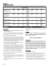
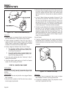
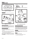
Figure 7-12. – Harness End of Connector 2
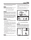
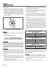
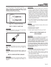
6. For LPG models, disconnect Wire 14A from the LPG Fuel
Solenoid (FS)(see Figure 7-13). Connect the VOM positive (+)
test lead to Wire 14A. Connect the VOM negative(-) test lead to
frame ground. Repeat Steps 4a and 4b. Battery Voltage
should be measured when the Primer Switch is activated.
7. Set the VOM to measure resistance at the “Rx1” scale and
zero the meter.
a. Disconnect Wire 14 from the Primer Switch.
b. Connect the meter test leads across the
Wires 14 and 14A terminals of the switch.
c. With the switch NOT actuated, the meter
should read
“
Continuity”
.


