


SSeeccttiioonn 55
EENNGGIINNEE DDCC CCOONNTTRROOLL SSYYSSTTEEMM
Page 20
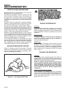
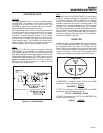
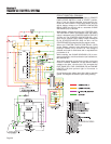
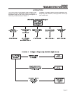
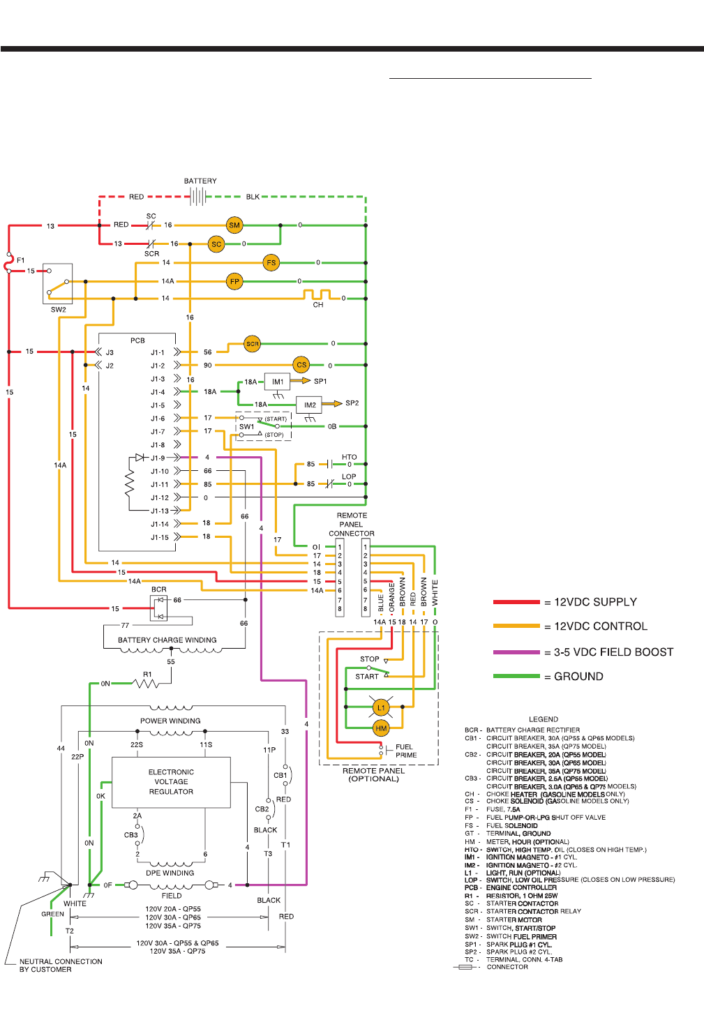
CIRCUIT CONDITION- CRANKING:
When the START-STOP-SWITCH (SW1)or REMOTE
PANEL START SWITCH is held at “START” position,
Wire 17 from the Engine controller circuit board is con-
nected to frame Ground. Circuit board action will then
deliver battery voltage to a STARTER CONTACTOR
RELAY (SCR) via wire 56, and to a automatic CHOKE
SOLENOID (CS) via Wire 90.
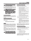
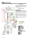
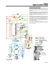
When battery voltage energizes the STARTER CON-
TACTOR RELAY (SCR), Its contacts close and battery
output is delivered to the STARTER CONTACTOR (SC)
via Wire 16. The STARTER CONTACTOR (SC) ener-
gizes and its contacts close, battery output is delivered
to the STARTER MOTOR (SM) via Wire 16.The
STARTER MOTOR energizes and the engine cranks.
When the STARTER CONTACTOR RELAY (SCR)
closes, Battery voltage is also delivered to the circuit
board pin location J1-13 via Wire 16. This voltage is
reduced and used for field boost and is outputted from
pin location J1-9.
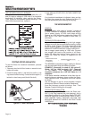
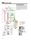
While cranking, the CHOKE SOLENOID (CS) is ener-
gized cyclically by circuit board action (two seconds on,
two seconds off).
Also while cranking, circuit board action energizes
CIRCUIT BOARD TERMINAL J2 and delivers battery
voltage to the Wire 14/14A circuit. This energizes the
FUEL PUMP (FP) ,FUEL SOLENOID (FS) and CHOKE
HEATER (CH) and optional light or hourmeter in
remote panel.
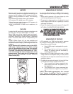
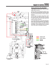
Circuit board action holds open Wire 18A to common
ground. The Magneto will induce a spark during cranking.