SSeeccttiioonn 55
EENNGGIINNEE DDCC CCOONNTTRROOLL SSYYSSTTEEMM
INTRODUCTION
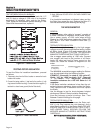
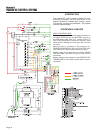
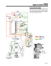
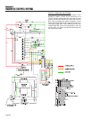
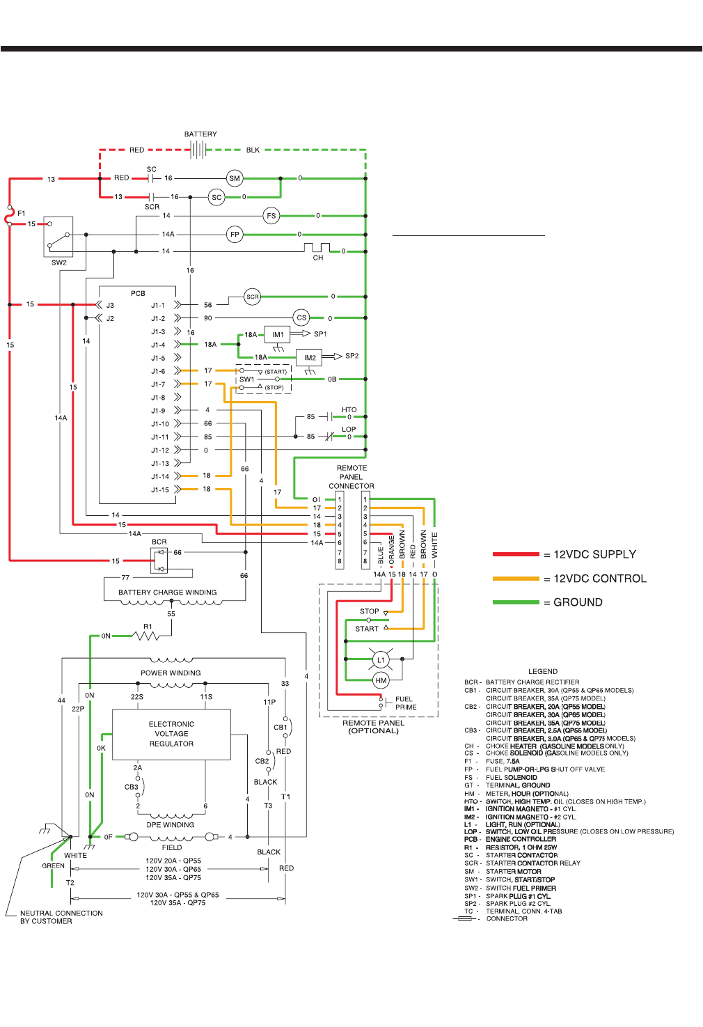
The engine DC control system includes all com-
ponents necessary for the operation of the
engine. Operation includes rest, priming, crank-
ing, starting, running and shutdown. The system
is shown schematically.
OPERATIONAL ANALYSIS
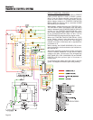
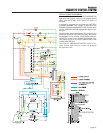
CIRCUIT CONDITION- REST:
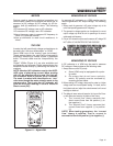
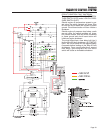
Battery voltage is available to the engine controller cir-
cuit board (PCB) from the unit BATTERY and via (a)
the RED battery cable, Wire 13, a 7.5 amp FUSE (F1),
Wire 15 and circuit board Terminal J3. However, circuit
board action is holding the circuit open and no action
can occur.
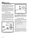
Battery output is available to the contacts of a
STARTER CONTACTOR (SC) and STARTER CON-
TACTOR RELAY (SCR), but the contacts are open.
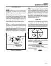
Battery voltage is also delivered to the FUEL PRIMER
SWITCH (SW2). The switch is open and the circuit is
incomplete.
Battery voltage is also available to the REMOTE FUEL
PRIMER SWITCH. The switch is open and the circuit is
incomplete.
Page 18


