SSeeccttiioonn 44
MMEEAASSUURRIINNGG EELLEECCTTRRIICCIITTYY
METERS
Devices used to measure electrical properties are
called meters. Meters are available that allow one to
measure (a) AC voltage, (b) DC voltage, (c) AC fre-
quency, and (d) resistance In ohms. The following
apply:
❏To measure AC voltage, use an AC voltmeter.
❏To measure DC voltage, use a DC voltmeter.
❏Use a frequency meter to measure AC frequency In
“Hertz” or “cycles per second”..
❏Use an ohmmeter to read circuit resistance, in
“ohms”.
THE VOM
A meter that will permit both voltage and resistance to
be read is the “volt-ohm-milliammeter” or “VOM”.
Some VOM's are of the “analog” type (not shown).
These meters display the value being measured by
physically deflecting a needle across a graduated
scale. The scale used must be Interpreted by the
user.
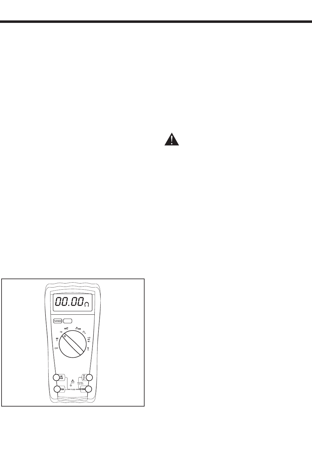
“Digital” VOM's (Figure 4-1) are also available and
are generally very accurate. Digital meters display the
measured values directly by converting the values to
numbers.
NOTE: Standard AC voltmeters react to the AVER-
AGE value of alternating current. When working
with AC, the effective value is used. For that rea-
son a different scale is used on an AC voltmeter.
The scale is marked with the effective or “rms”
value even though the meter actually reacts to the
average value. That is why the AC voltmeter will
give an Incorrect reading if used to measure
direct current (DC).
Figure 4-1. – Digital VOM
MEASURING AC VOLTAGE
An accurate AC voltmeter or a VOM may be used to
read the generator's AC output voltage. The following
apply:
1. Always read the generator's AC output voltage only at the
unit's rated operating speed and AC frequency.
2. The generator's voltage regulator can be adjusted for correct
output voltage only while the unit is operating at its correct
rated speed and frequency.
3. Only an AC voltmeter may be used to measure AC voltage. DO
NOT USE A DC VOLTMETER FOR THIS PURPOSE.
DDAANNGGEERR!!:: RRVV GGEENNEERRAATTOORRSS PPRROODDUUCCEE HHIIGGHH
AANNDD DDAANNGGEERROOUUSS VVOOLLTTAAGGEESS.. CCOONNTTAACCTT
WWIITTHH HHIIGGHH VVOOLLTTAAGGEE TTEERRMMIINNAALLSS WWIILLLL
RREESSUULLTT IINN DDAANNGGEERROOUUSS AANNDD PPOOSSSSIIBBLLYY
LLEETTHHAALL EELLEECCTTRRIICCAALL SSHHOOCCKK..
MEASURING DC VOLTAGE
A DC voltmeter or a VOM may be used to measure
DC voltages. Always observe the following rules:
1. Always observe correct DC polarity.
a. Some VOM's may be equipped with a polar-
ity switch.
b. On meters that do not have a polarity
switch, DC polarity must be reversed by
reversing the test leads.
2. Before reading a DC voltage, always set the meter to a higher
voltage scale than the anticipated reading. if in doubt, start at
the highest scale and adjust the scale downward until correct
readings are obtained.
3. The design of some meters is based on the “current flow” theo-
ry while others are based on the “electron flow” theory.
a. The “current flow” theory assumes that
direct current flows from the positive (+) to
the negative (-).
b. The “electron flow” theory assumes that
current flows from negative (-) to positive
(+).
NOTE: When testing generators, the “current
flow” theory is applied. That is, current is
assumed to flow from positive (+) to negative (-).
Page 15
