SSeeccttiioonn 55
EENNGGIINNEE DDCC CCOONNTTRROOLL SSYYSSTTEEMM
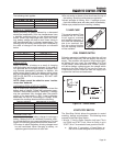
The following chart applies:
CCAABBLLEE LLEENNGGTTHH ((IINN FFEEEETT)) RREECCOOMMMMEENNDDEEDD CCAABBLLEE SSIIZZEE
0-10 No. 2
11-15 No. 0
16-20 No. 000
EFFECTS OF TEMPERATURE:
Battery efficiency is greatly reduced by a decreased
electrolyte temperature. Such low temperatures have
a decided numbing effect on the electrochemical
action. Under high discharge rates (such as crank-
ing), battery voltage will drop to much lower values in
cold temperatures than in warmer temperatures. The
freezing point of battery electrolyte fluid is affected by
the state of charge of the electrolyte as indicated
below:
SSPPEECCIIFFIICC GGRRAAVVIITTYY FFRREEEEZZIINNGG PPOOIINNTT
1.220 -35° F. (-37° C.)
1.200 --20° F. (-29° C.)
1.160 0° F. (-18° C.)
ADDING WATER:
Water is lost from a battery as a result of charging
and discharging and must be replaced. If the water is
not replaced and the plates become exposed, they
may become permanently sulfated. In addition, the
plates cannot take full part in the battery action unless
they are completely immersed in electrolyte. Add only
DISTILLED WATER to the battery. DO NOT USE
TAP WATER.
NOTE: Water cannot be added to some “mainte-
nance-free” batteries.
CHECKING BATTERY STATE OF CHARGE:
Use an automotive type battery hydrometer to test the
battery state of charge. Follow the hydrometer manu-
facturer's instructions carefully. Generally, a battery
may be considered fully charged when the specific
gravity of its electrolyte is 1.260. If the hydrometer
used does not have a “Percentage of Charge” scale,
compare the readings obtained with the following:
SSPPEECCIIFFIICC GGRRAAVVIITTYY PPEERRCCEENNTTAAGGEE OOFF CCHHAARRGGEE
1.260 100%
1.230 75%
1.200 50%
1.170 25%
CHARGING A BATTERY:
Use an automotive type battery charger to recharge a
battery. Battery fluid is an extremely corrosive, sulfu-
ric acid solution that can cause severe burns. For that
reason, the following precautions must be observed:
❏The area in which the battery is being charged must
be well ventilated. When charging a battery, an
explosive gas mixture forms in each cell.
❏Do not smoke or break a live circuit near the top of
the battery. Sparking could cause an explosion.
❏Avoid spillage of battery fluid. If spillage occurs,
flush the affected area with clear water immediately.
❏Wear eye protection when handling a battery.
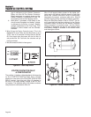
7.5 AMP FUSE
This panel-mounted Fuse
protects the DC control
circuit against overload
and possible damage. If
the Fuse has melted open
due to an overload, nei-
ther the priming function
nor the cranking function
will be available.
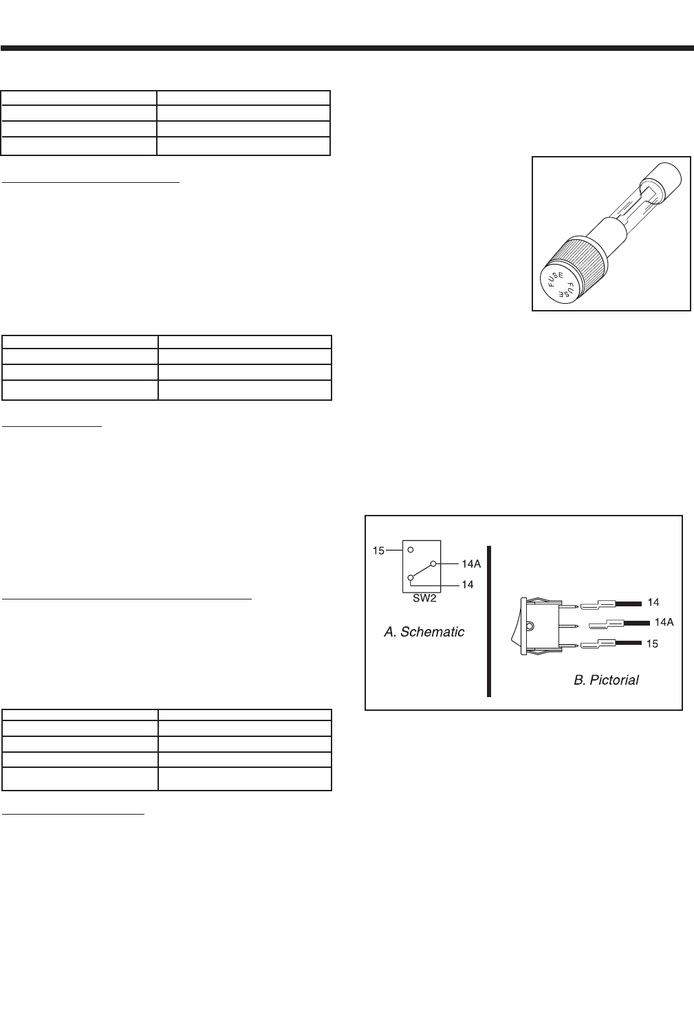
FUEL PRIMER SWITCH
Following generator installation and after the unit has
been idle for some time, the fuel supply line may be
empty. This condition will require a long cranking peri-
od before fuel can reach the carburetor. The Fuel
Primer Switch, when actuated to its “PRIME” position
will deliver battery voltage across the closed switch
contacts to the Fuel Pump (FP) to turn the Pump on.
Pump action will then draw fuel from the supply tank
to prime the fuel lines and carburetor.
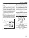
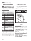
Figure 5-5. – Primer Switch
START-STOP SWITCH
The Start-Stop Switch allows the operator to control
cranking, startup and shutdown. The following wires
connect to the Start-Stop Switch:
1. Wire No. 17 from the Engine Controller circuit board. This Is
the CRANK and START circuit. When the Switch is set to
'START”, Wire 17 is connected to frame ground via Wire OB.
a. With wire 17 grounded, a Crank Relay on
the circuit board energizes and battery volt-
Page 25
Figure5-4


