


Section 4. ET106 Sensor Arm Installation
4-6
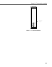
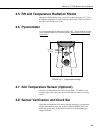
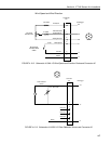
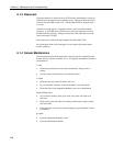
FIGURE 4.9-3. Installing Leveling Screws
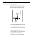
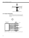
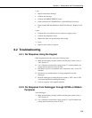
4.10 Sensor Schematics
Schematics of ET106 sensors and associated connectors are provided in
Figures 4.10-1, 4.10-2, 4.10-3, and 4.10-4 for help in troubleshooting.
Knowledge of the schematics is not necessary for routine installation and
maintenance.
1
2
3
4
5
6
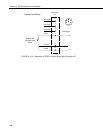
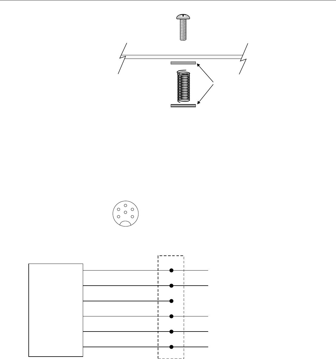
Air Temperature and
Relative Humidity
Sensor
Connector
Pin
Datalogger
Relative Humidity (0-1VDC)
Air Temperature (0-1VDC)
12V Switched Supply
Not Used
Analog Ground
Shield
1
2
3
4
5
6
1 H
1 L
12VDC Switched
Supply
AG
G
FIGURE 4.10-1. Schematic of CS500-LC RH and Temperature Probe and Connector #1
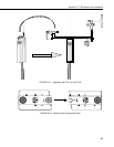
Metal Washers