


Section 3. ET Instrumentation Installation
3-11
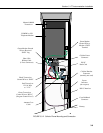
3.3.3.1 Internal Installation
For installation inside the ET Enclosure, the following components are
provided in the short-haul modem kit:
(1) SC932C Interface
(1) Rad Modem
(1) Rad/SC932C Mounting Bracket
(4) Screws
(1) 12 inch 4-wire patch cable
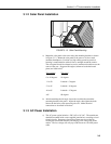
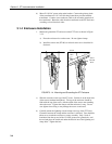
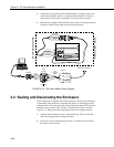
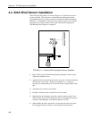
Install the short-haul modems as shown in Figure 3.3-4 and 3.3-5.
1. Mount the Rad / SC932C mounting bracket into the ET Enclosure with the
3 pre-threaded screws provided.
2. Connect the Rad Modem and SC932C. Strap them into the mounting
bracket under the Velcro strap.
3. Connect the SC932C 9-pin port to the internal ET Enclosure 9-pin port
with the blue ribbon cable provided.
4. Wire the Rad Modem to the ET Enclosure with the 12-inch patch cord.
Match wire labels to wiring panel labels on both the ET Enclosure and the
Rad Modem (+XMT to +XMT, etc.). A small screwdriver in provided
with the ET Enclosure to access the Rad Modem connections.
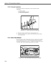
3.3.3.2 External Installation
The following short-haul kit components are used to make the external
connections:
At the ET Enclosure:
(1) 20 foot 4-Wire Patch Cable
(2) 2 Direct Bury Splice Kits
(1) Length of User Supplied Wire (Supplier: Anixter, p/n F-02P22BPN,
Phone 847-677-2600)
At the PC:
(1) Rad Modem
(1) 5 foot 4-wire Patch Cable
(1) 10 foot 14 AWG Ground Wire
(1) Surge Protector and Case
1) Connect the 20 foot patch cable to connector #8 on the external back panel
of the ET Enclosure. Splice this cable to the user supplied cable, using the
direct bury splice kits.
2) Mount the surge protector to a flat surface within 10 inches of the PC's
serial port. Ground the center terminal to an earth (or building) ground
using the 14 AWG wire.