


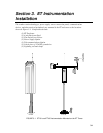
Section 3. ET Instrumentation Installation
3-4
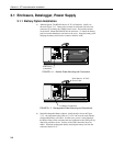
b) Shut off 110 VAC power at the main breaker. Connect the primary leads
of the transformer to 110 VAC following instructions provided with the
transformer. Connect a two-conductor cable to the secondary terminals of
the transformer. Route the cable from the transformer to the ET Enclosure
according to local electrical codes.
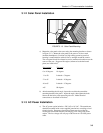
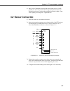
3.1.4 Enclosure Installation
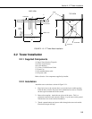
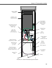
1. Mount and ground the ET enclosure on the ET Tower as shown in Figure
3.1-4.
a) Place the enclosure low on the tower. Do not tighten clamps.
b) Install the sensor arm (ET106) or reduced sensor set as described in
Section 4.
NORTH
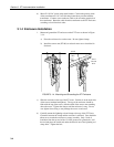
FIGURE 3.1-4. Mounting and Grounding the ET Enclosure
c) Slide the enclosure to the top of the ET tower. Position it on the north side
of the tower (northern hemisphere). The top of the enclosure should be
flush with the top of the tower, with the width of the sensor arm extending
above the tower. Tighten the clamps until the enclosure is snug. Do not
over-tighten since doing so may damage the tower or enclosure.
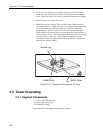
d) Carefully mount the lightning rod and clamp to the top of the ET Tower.
Clearance between the clamp and the enclosure is minimal. Care should be
taken not to scratch the enclosure or sensor assembly. Strip 1 inch of
insulation from the top end of the 12 AWG green tower ground wire, curl
the end and place the curled end under the head of one of the lightning rod
clamp bolts. Tighten the bolt.
9-inch
Ground
Wire
Tower
Ground
Wire