


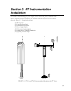
Section 2. ET Tower Installation
2-3
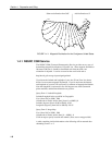
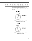
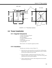
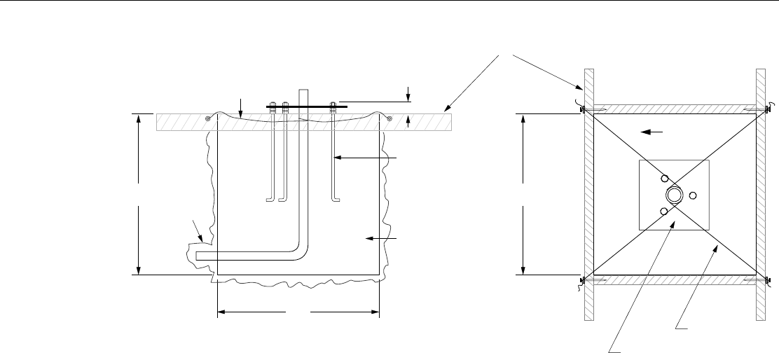
SIDE VIEW
TOP VIEW
ANCHOR BOLT
FORM
FORM WIRE
CEMENT PAD
SMALL
CAVITY
24"
24"
24"
TEMPLATE
2"
NORTH
FORM WIRE
FIGURE 2.1-2. ET Tower Base Installation
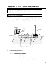
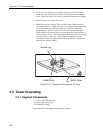
2.2 Tower Installation
2.2.1 Supplied Components
(1) Upper Tower Section (Tapered)
(1) Lower Tower Section
(6) ½ inch Washers
(1) 12 foot 12 AWG Ground Cable
(1) Tower Cap
(1) 20' communications cable
(1) 20' power cable
Refer to Section 1 for components supplied by installer.
2.2.2 Installation
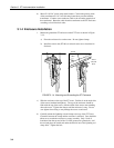
Attach the tower to the base as shown in Figure 2.2-1.
1. Dig a hole close to the concrete base to access the lower conduit opening.
From the hole, trench to the power and communications sources. Remove
the duct tape from both ends of the conduit.
2. Remove the template. Attach the two pieces of the tower. This is a
permanent connection and cannot be undone. Lay the tower on the ground
with the base next to the concrete foundation.
3. Thread communications and power cables through the tower and conduit.
Electrical fish tape will help.