


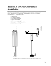


Section 3. ET Instrumentation Installation
3-8
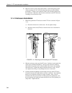
3.3.2.1 Internal Installation
For installation inside the ET Enclosure, the following components are
provided in the cell phone modem kit:
(1) COM100 Transceiver, Power Connector
(1) Mounting Bracket
(6) Screws
(1) 12 inch Coaxial Patch Cable
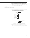
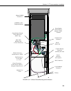
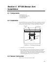
Install the phone modem and cellular transceiver as shown in Figure 3.3-2.
1. Attach the modem to the modem bracket with 4 of the screws provided.
Attach the cellular transceiver with 2 of the screws provided. Mount the
bracket into the ET Enclosure with the 3 pre-threaded screws on the
mounting plate.
2. Mount the RJ11C Interface to the side of the battery bracket.
3. Connect the modem 9-pin port to the ET Enclosure port with the blue 9 pin
ribbon cable supplied with the ET Enclosure.
4. Connect the modem RJ-ll jack to the RJ11C Interface with the RJ-ll patch
cord. Connect the cellular transceiver coaxial connection to the bulkhead
coaxial connector with the coaxial patch cable.
5. Connect the modem ground terminal to the recessed ET Enclosure ground
with the 14 AWG ground wire.
6. Do this step after the antenna is connected (Section 3.3.2.2). Connect the
transceiver power cord assembly to the transceiver's 25 pin connector.
Connect the red 12 V lead to the 12V terminal in the ET Enclosure.
Connect the black ground lead to the GND terminal. Connect the green
power control lead to the RCV+ and terminal.