


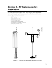
Section 3. ET Instrumentation Installation
3-5
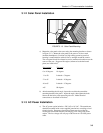
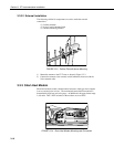
e) Strip 1 inch of insulation from each end of the 9-inch piece of 12 AWG
ground wire. Insert one end into the brass ground lug located at the top
back of the enclosure. Curl the other end and place under the head of one
of the lightning rod clamp bolts. Tighten the bolt.
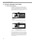
3.2 Sensor Connection
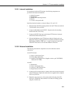
1) Install the sensor set as described in Section 4.
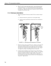
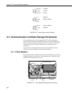
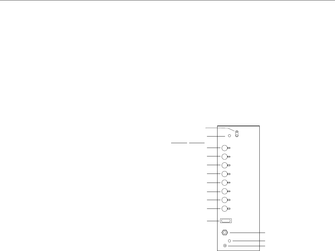
2) Remove the protective connector cover from the back of the ET Enclosure
by removing the two Phillips head screws. Sensors connect to one of
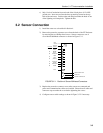
seven labeled bulkhead connectors as shown in Figure 3.2-1.
Earth
Ground
Stand off
Connector
#4
Sensors
TEMP
CS615
TEMP
RAIN
(PRECIP)
TEMP / RH
SOLAR
RADIATION
COMM
WS/WD
SDI 12
GYP BLOCK
#2
#6
#7
#5
#1
#3
#8
CS I/O
POWER CABLE PORT
STAND OFF
COAXIAL CONNECTION
FIGURE 3.2-1. Position of Sensor Bulkhead Connectors
3) Replace the protective connector cover after sensors are connected and
power and communications cables are installed. Ensure that all cables and
connector caps are under the cover before tightening the screws.
4) Configure sensor switch settings as shown in Figure 3.2-2 if necessary.