Section 4. ET106 Sensor Arm Installation
4-3
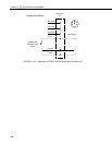
4.5 RH and Temperature Radiation Shield
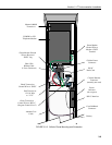
Mount the radiation shield to the sensor arm as shown in Figure 4.4-1. Place
the RH and temperature assembly inside the shield shaft. Attach the shield to
the sensor arm with the two screws.
4.6 Pyranometer
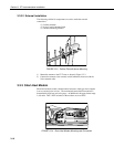
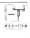
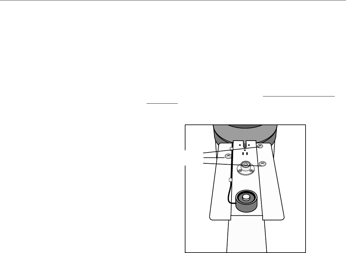
Level the pyranometer as indicated in Figure 4.6-1. Adjust the three leveling
screws until the bubble level indicates plumb. Remove the red cap from the
pyranometer.
FIGURE 4.6-1. Pyranometer Leveling
4.7 Soil Temperature Sensor (Optional)
Bury the soil temperature sensor at the desired depth. To minimize solar
loading of the sensor cable, bury the cable between the tower base and the
sensor.
4.8 Sensor Verification and Clock Set
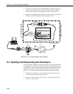
Check the measurements of all sensors after the datalogger is programmed.
Display measurements using the *6 Mode with the CR10KD (refer to the
laminated prompt sheet, or the Monitor Mode of the PC208 Datalogger
Support Software.
Leveling
Screws


