


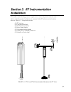

Section 2. ET Tower Installation
2-2
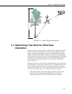
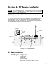
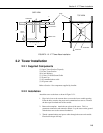
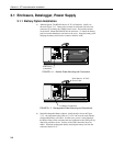
2.1.2 Installation
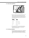
1. The ET Tower attaches to a user supplied concrete foundation constructed
as shown in Figure 2.1-2.
2. Construct the concrete form with 2" x 4" lumber and 16p nails.
3. Assemble the template and anchor bolts. There should be two nuts below
and one nut above the template on each bolt.
4. Clear an area large enough to set the form at the desired elevation.
5. Dig a hole 2 feet x 2 feet x 2 feet. Lighter soils may require a deeper hole.
About 20 inches below the top of the hole, gouge a small cavity in one wall
of the hole. The cavity should be about 4 inches deep and just large
enough in diameter to insert one end of the conduit. Make certain the
cavity "points" in the direction from which power and communications
cables will come.
6. Center the form over the hole. Adjacent to the form, drive four stakes into
the soil. Secure the leveled form to the stakes with the 8p nails.
7. Cap the ends of the conduit with duct tape. Position the conduit and wire
into place by securing the wire to nails in the form.
8. Fill the hole and form with approximately ½ yard of concrete. Screed the
concrete level with the top of the form. Center the template assembly over
the conduit and press into the concrete. Put 2 x 4 spacers between the
template and the top of the form. The bottom of the bolt threads should be
about ½ inch above the concrete. The template must be level in two
dimensions. Use a trowel and edger to finish.
9. Wait 24 hours before removing the concrete form. Wait 7 days before
mounting the ET Tower.