


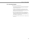


Section 3. ET Instrumentation Installation
3-7
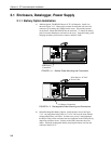
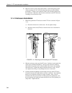
3.3.1.1 Internal Installation
For installation inside the ET Enclosure, the following components are
provided in the phone modem kit:
(1) COM200 or COM300 Phone Modem
(1) 12 inch RJ-11 Patch Cord
(1) Mounting Bracket
(4) Screws
(1) 12 inch 14 AWG Ground Wire
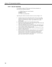
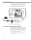
Install the phone modem as shown in Figure 3.3-1.
1. Attach the modem to the modem bracket with the 4 screws provided.
Mount the modem and bracket into the ET Enclosure with the 3 pre-
threaded screws on the mounting plate.
2. Connect the modem 9-pin port to the ET Enclosure port with the
P/N 10588 ribbon cable supplied with the ET Enclosure.
3. Connect the modem RJ-ll jack to the ET Enclosure RJ-11 jack with the RJ-
ll patch cord.
4. Connect the modem ground port to the ET Enclosure ground with the 14
AWG ground wire.
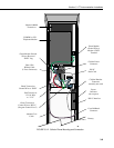
3.3.1.2 External Installation
The following modem kit components are used to make the external
connections:
(1) Direct Bury Splice Kit
(1) 20 foot Telephone Patch Cord with Connector
1) Connect the 20 foot patch cord to connector #8 on the external back panel,
under the protective cover.
2) Splice the labeled "Tip" and "Ring" lines of the patch cord to the telephone
service line. Use the direct bury splice kit when splices are in a valve box
or buried.
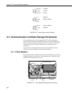
3.3.2 Cellular Phone Transceiver
Do not power the transceiver until the antenna is
connected!
Cellular service and programming of your transceiver must be coordinated with
your local cellular provider. Cellular service enables communication between
the ET Enclosure and the Hayes compatible modem at your PC without
hardwire connections. The cellular transceiver kit must be purchased with one
of the phone modem kits.
CAUTION