


Appendix
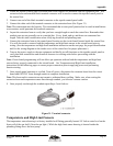
Both of these sensors are delivered inside the control box with the extension loom. Identifying and connecting
the two sensors in the correct location on the circuit board is very important. Sensors located incorrectly, will
cause the spa to operate incorrectly and could result in spa damage.
Identifying and Installation
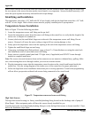
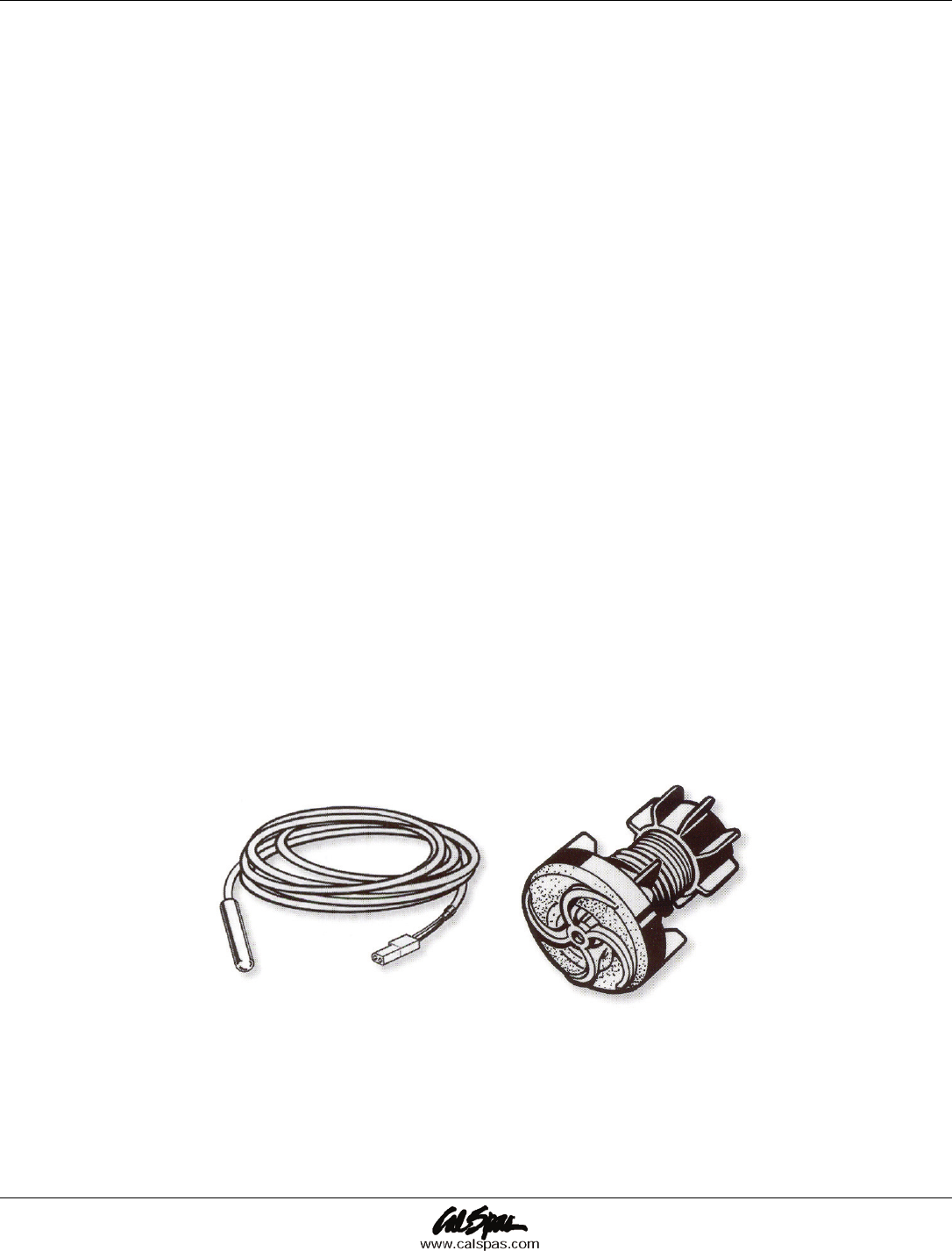
The temperature sensor has a 3/8” bulb with 50' of wire length, while the the high limit sensor has a 1/4” bulb
with 48” of wire length. Both of these sensors must be properly installed prior to spa operation.
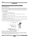
Temperature Sensor Installation
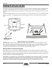
Refer to Figure 32 for the following procedure.
1. Locate the temperature sensor wall fitting on the spa shell
2. Layout the temperature sensor from the sensor wall fitting to the control box to verify that the length of the
sensor wire is adequate for conduit run
3. Loosen (clockwise) the small black finger nut at the end of the temperature sensor wall fitting. Do not
remove. Removal will cause the water sealing o-ring to fall out, causing damage or loss.
4. Firmly press the temperature sensor into the opening at the end of the temperature sensor wall fitting.
5. Tighten the small black finger nut until snug.
6. Using spray insulating foam (Polyurethane), spray at least 6” of foam thickness covering the entire back
side (installation side) of sensor and sensor wall fitting.
7. Secure sensor to topside control panel and 12V light wires (if applicable) and GENTLY route through
conduit to complete installation.
Note: The sensor wires and extension loom and its connector are not meant to withstand heavy pulling. Make
sure, when routing these wires through conduit, you exercise extreme caution.
8. Plug the temperature sensor into the temperature sensor location on the circuit board located inside the
control box. (See the wiring diagram on the inside cover of the control box for proper placement.)
9. Follow the high limit sensor installation instructions prior to testing operation. Circuit board programming
will not allow spa operation without both sensors being connected to the circuit board.
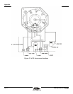
Figure 32. Temperature sensor and sensor wall fitting
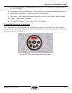
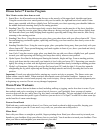
High Limit Sensors
The high limit sensor housing is a factory installed plumbing fitting located on the discharge side of pump #1
(Heat Pump). Most equipment packs will have this sensor already installed for you.
Page 66 2005 Spa Owner's Manual
Visually inspect the circuit board and plumbing fitting to verify the high limit sensor is already installed. If not,
follow the installation steps below.
8/1/2005