


© 2004 Alamo Group Inc.
Page 7 - 4
Interstater (NH TS-100A , 115A , 125A & 135A Asy. Manual) 06/04
Wing Mower Installation
Wing Cut Off Switch: (continued)
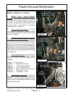
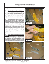
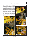
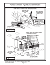
5. Install Mower Front Mounting Brackets. The
Mower Hinge Front Bracket has a has a LH & RH
(See Figure 10). These brackets will slide over the
Hinge Pin which is bolted to the mower deck at the
factory. This bracket will be bolted to the Lift frame
with four bolts. This hinge Pin WILL NOT have threaded
holes as the rear hinge pin did.
6. Install Wing Mower to Lift Frame. Using the
over head hoist position the Mower Deck (See Figure
10) to where the front hinge bracket will align with the
lift frame. Install at least two of the mounting bolts and
snug them down.
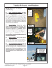
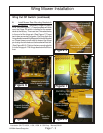
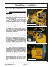
7. Install the wire harness to wings. The Wire
harness will have a lead to each wing. These can be
determined by the length, the longer lead will go to the
left wing. There is apiece of square tube welded to the
lift frame on the back for the wire harness to be run
through (See Figure 11). The wire harness will be run
down and under the round bar of lift frame. Leave
harness here for now.
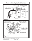
8. Install Magnetic Switch Pickup & Bracket as
well as the rear hinge bracket. The Rear hinge
Bracket will install similar to the way the front does,
but not the same because the Magnetic switches and
brackets bolt on with it. Before installing the rear
Hinge bracket locate the magnetic Switch Bracket
(See Figure 12). There are two spacers about 3/4"
long that must be installed between the magnetic
switch bracket and the hinge Bracket (See Figure
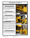
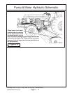
12), Also the wire harness must be run between
these two spacers and between these two brackets
(See Figure 13 & 14). Install the remaining two bolts
and tighten all the hinge bracket bolts, this will include
the front hinge bracket bolts. (See Figure 21)
9. Plug Magnetic Switch into Wire Harness. The
wire harness should have a plug that aligns with the
magnetic switch wire. Plug these together now and
continued to run wire harness up behind the hinge
and on up to the mower decks motor. (See Figure 21)
Figure 10
LH Wing Front Hinge
Pin Bracket
LH Wing Shown
From Front
Figure 11
Figure 12
LH Wing Shown
From Front
LH Wing Shown
From Front