


© 2004 Alamo Group Inc.
Page 2 - 4
Interstater (NH TS-100A , 115A , 125A & 135A Asy. Manual) 06/04
Main Frame Dual / Single Wing
Mount Frame Rails To Tractor:
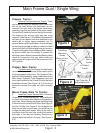
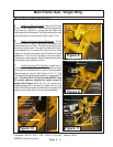
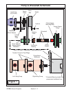
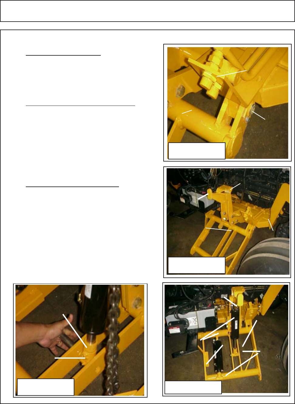
5. Install LH Wing Lift frame. The wing lift frame
pivots on two hinge pins. When installing these pins
they must be aligned in a way that will allow the
retaining bolt to be installed. The Right side and the Left
side will install in the same way (See Figure 7 & 8)
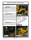
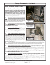
6. Install Lift Cylinder Mount Weldment . The lift
cylinder mount is a bolt on weldment that bolts to the
main frame with four bolts. The Left Hand and the right
hand are not the same. The right hand side will have a
mount welded to it to mount the control valve to (See
Figure 8), the left hand mount will not have this plate
welded to it. The LH & RH will bolt on the same way.
Tighten the mounting bolts. Note the bracket also have
the transport lugs welded to them.
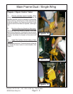
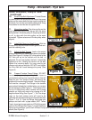
7. Install the Lift and Tilt Cylinders. Install the Lift
cylinder and the Tilt Cylinder. When installing these
they must be installed with the rod end clevis grease
fitting facing up and out (See Figure 10 & 11). The
Cylinder for the Left Wing will install the same as the RH
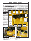
side. The Wing RH & LH Lift Cylinders MUST have
lift control spacers installed to control wing lift
height (See Figure 10 & 11). Do not remove any
shipping plugs from cylinders or hoses until you are
ready to install the hoses, this will keep the system and
components clean while unit is being assembled.
Figure 8
Hinge
Pin
Wing Lift
frame
Hyd Tube
Assembly
RH Side
Front
Shown
Figure 9
RH Wing Lift Cylinder Mounting
Weldment with valve mounting plate
welded to it
Transport
lug
Wing Lift
Frame
Mainframe
Wing Lift Cylinder
Figure 11
Wing Fold
Cyl.
Install with
Hyd. fittings
to rear
Grease
Fittings
must face
up.
Figure 10
Grease
Fittings
must face
up & out
Lift Control
Spacer
Lift Control
Spacer must be
installed on Lift
Cylinders