


© 2004 Alamo Group Inc.
Section 3 - 9
Interstater (NH TS-100A , 115A , 125A & 135A Asy. Manual) 06/04
Pump - Driveshaft - Hyd tank
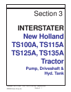
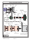
Figure 22
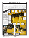
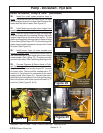
26. Install the small pump pressure hose to
pump. The pressure hose connects to the RH side
of the small pump and is run down the RH side of the
frame with the return hoses (See Figure 21)
27. Install sleeving over the return hoses from
heads and control valve and Control valve Pressure
Hose. Slide the three hoses through the sleeving.
Slide the hoses with the sleeving through the hose
support ring bolted to the side of the tractor. Tie the
sleeving using plastic ties around the hoses to keep
it from moving (See Figure 22). Tie the sleeving with
plastic ties around the pressure hose on the LH side
of tractor (See Figure 13)
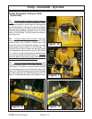
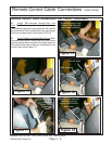
28. Install return hose to cross member and
Hoses to Control Valve. Connect the return hose to
the cross member on right hand side of main frame
crossmember (See Figure 23). The other end will
connect to the return filter Tee fitting (See Figure 24)
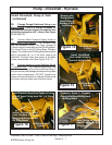
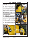
29. Connect Pressure & Return Hose to Cylin-
der Control valve. Connect the pressure hose run-
ning from the RH side of small pump to RH Top side
of control valve, The port will be marked with a "P"
cast into it, the other end is connected to the small
supply pump (See Figure 21). Connect the return
hose that is connected to the Tee Fitting of the return
filter to the Return side of the control valve with a "T"
cast into it (See Figure 24 & 25)
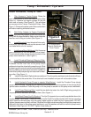
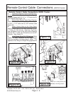
Figure 23
Return Hose
from Wing
Motors to Tank
Pressure Hose
to RH Wing
Motor
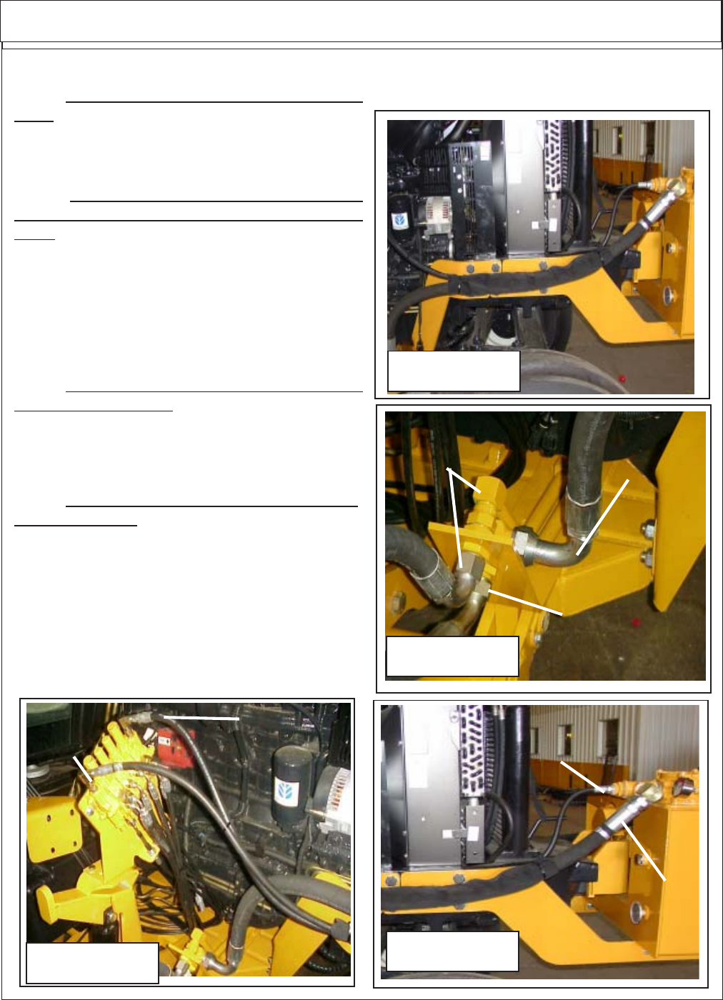
Return Line From
RH Wing Deck
Cooling Tanks
"In" Pressure
Side
"Out" Return
Side
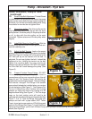
Figure 24
Install Driveshaft, Pump & Tank: (continued)
Return Hose from
Hyd Valve "T" Port
Return Hose from Main
Frame Crossmember
(Motor Return)
Figure 25