


© 2004 Alamo Group Inc.
Page 2 - 2
Interstater (NH TS-100A , 115A , 125A & 135A Asy. Manual) 06/04
Main Frame Dual / Single Wing
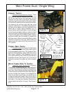
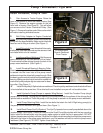
Prepare Tractor:
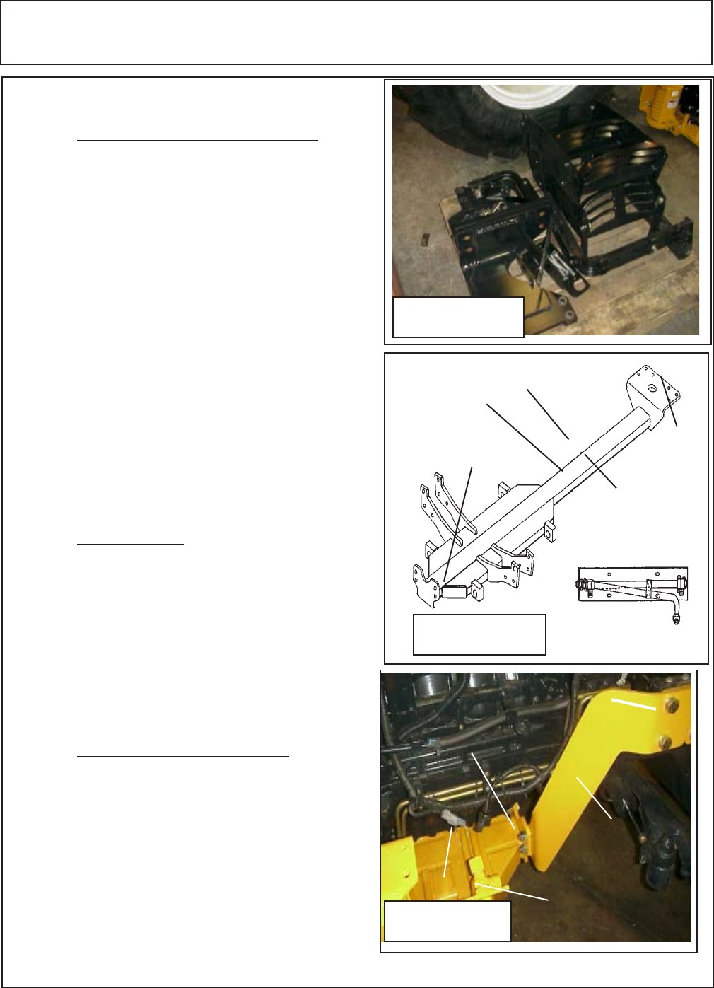
Remove Components from Tractor. There
are items that must be removed from tractor that
will not be used before the mainframe can be
mounted. On each side of the tractor there heavy
mounting lugs that are bolted to the tractor frame.
One on the left hand and one on the right hand side.
The steps on the left and right side has to be
removed. (See Figure 1) The Battery Relocation Kit
will have to be installed, with this modification the
battery will no longer swing completely out. To
remove Battery after modification is done will best
be done by two people as battery is heavy and will
have to be lifted out. Before beginning any work on
Tractor the Negative Ground Batterycable needs to
be disconnected from the battery to protect the
electrical system. Before reconnecting Battery cable
check all connections that you have made and
make certain all components of the tractor are in the
OFF position.
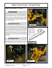
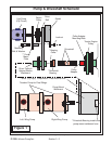
Prepare Main Frame:
The Main frame (See Figure 2) will be bolted
up under the tractor at the rear of the tractor and to
the frame support rails at front. The Hydraulic Tube
bracket & tube assembly needs to be bolted to the
Main frame. Hydraulic Tube Assembly has a left
and a right hand side, the LH and RH side has to be
installed as shown (See Figure 2 & 3). If this is not
bolted on correctly the hoses will not fit correctly
later.
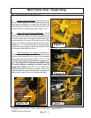
Mount Frame Rails To Tractor:
1. Install the Frame Mounts Rails. There is a
LH and a RH Frame Mounting rail. These will bolt to
the front of the tractor with three mounting bolts on
each side. When Starting the three mounting bolts
it will work best to install the RH Side (See Figure 2)
and the LH Side (See Figure 3). Do not tighten the
three mount bolts on each side , this will allow you
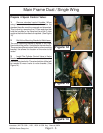
to align mounting bolts easier. Move to the rear of
the tractor under the rear axle, check the threaded
bolt holes in the rear end housing. Remove any
plugs or bolts that will be in the way. (See Figure 4
& 5)
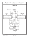
Figure 3
Frame mounting
rails bolt to
tractor
Mainframe to
frame rail mount-
ing bolts
Frame Mount-
ing Rails RH
Side
Mainframe
Hyd Tube Asy.
Bolted on
Dual Wing
Mainframe
Shown
RH Side of
Tractor
LH Side of
Tractor
Mount to
Rear of
Tractor
RH Side LH Side
Hyd. Tube Asy,
Bolt to Mainframe
Mount to Front
of Tractor
Figure 2
Figure 1
Removed Tractor
Parts that will not be
used