


© 2004 Alamo Group Inc.
Section 3 - 5
Interstater (NH TS-100A , 115A , 125A & 135A Asy. Manual) 06/04
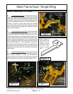
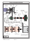
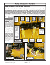
Figure 7
Pressure
Out Port
To LH
Wing
Motor,
Straight
Fitting
shown will
be changed
to Elbow
Fitting
Pressure
Out Port
To RH
Wing Motor
Suction
Port
From
Tank
Suction
Port
From
Tank
Case
Drain To
Tank
Case
Drain To
Tank
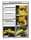
Tank Suction
Port, LH
Wing Pump
Suction
Port
From
Tank
Tank Suction
Port, RH
Wing Pump
Tank Suction
Port, Small
Pump
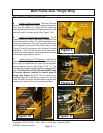
Figure 9
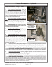
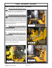
Pump - Driveshaft - Hyd tank
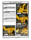
Pipe Sealer
Tube
Fitting with
Pipe Thread
Figure 8
Change to
Elbow Fitting
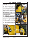
Install Driveshaft, Pump & Tank: (continued)
15. Connect Pump Case Drain To Tank. On the Right Hand side of the tandem pump there will be
two small elbows, these are the case drains for the pumps. On the side of the tank and above theses
elbows there will be two small plugs screwed into tank. Remove these plugs and install the pipe thread
end of the two small hose after coating the threads with pipe sealer. Connect the other end of the hose
to the elbows on the side of the pumps. NOTE: Only the Tandem pump will have case drains, the smaller
pump used to power the hydraulic cylinder system will not use a case drain. (See Figure 9 & 11)
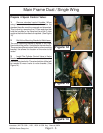
Return Tank
Ports for
Tandem
Pump Case
Drains
Case drain
Hoses laying
here for now
Install 90 degree
elbows and hose
barbs to suctiion
tubes from tank
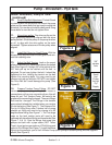
16. The small
pump used to supply
the cylinder hydrau-
lic system will have a
short hose that con-
nects to the small
pump and to the tank
suction port that is in
the tank exclusively
for the small pump.
This hose needs to
be cut to fit, do not
install with any kinks
in hose. (See Figure
6 & 7) which shows
these ports.Make
certain the Elbow
(pressure port of
outer tandem pump
(See Figure 9) is in-
stalled and tightened
pointing to the rear of
the pump.