


© 2004 Alamo Group Inc.
Section 3 - 3
Interstater (NH TS-100A , 115A , 125A & 135A Asy. Manual) 06/04
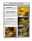
Existing Holes
have rubber
Plugs in them
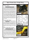
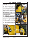
Figure 2
Air After-Cooler
Tractor
Bolster
Cover removed
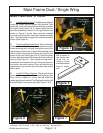
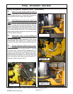
Figure 3
LH Side Engine
Guards Removed
From Tractor
Pump - Driveshaft - Hyd tank
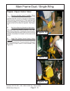
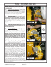
Install Driveshaft, Pump & Tank:
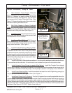
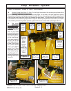
1. Gain Access to Tractor Engine. Raise the
hood of the tractor to revel the tractor engine (See
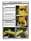
Figure 2). Remove the engine guards on the left
hand side of tractor (See Figure 3). This will allow
you access to the Tractor Crankshaft Pulley. (See
Figure 1). Remove the plate under After cooler which
will make installing driveshaft easier.
2. Bolt Pulley Adapter to Engine Crankshaft
Pulley. Bolt the pulley adapter to the to the crankshaft
pulley with the supplied bolts. Make certain the bolts
used are not to long or to short (See Figure 1).
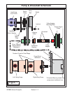
3. Install Driveshaft. Insert driveshaft into crank-
shaft pulley, both splined ends are the same so it will
not matter which end is inserted.
4. Install pump Mount Weldment. Bolt the pump
mount weldment to the front bolster of the tractor.
The driveshaft will be sicking through the hole in the
pump mount weldment. (See Figure 1)
5. Install Driveshaft Bearing & Bearing Collar.
Slide the bearing onto the driveshaft until the bearing
is seated into the inner hole of the pump mount
weldment where the driveshaft comes through. Slide
the bearing collar onto driveshaft until seated against
bearing. Making certain that driveshaft is seated into
crankshaft pulley adapter tighten setscrew for bear-
ing collar. (See Figure 1)
6. Install Drive pulley & Splined sleeve weldment. The drive pulley weldment and drive belt will have
to be installed at the same time. If the drive belt is not installed now you will not be able to later.
7. Install Hydraulic Pump (Pumps to operate Wing Motors). Install the Tandem Pump (single
pump if only one wing.) By aligning the splines of the pump shaft with the splines of the drive pulley &
splined sleeve weldment. Push the pump on till the pump is seated into the pump mount weldment.
8. Install Pump Retaining Bolts. Install the two bolts that retain the Left & Right wing pump(s) to
the pump mount weldment and tighten them. (See Figure 1)
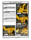
9. Install Small Pump (Hyd Cyl System). The Hyd Cyl operate from a small pump bolted above the
tandem pump. (See Figure 1) Bolt the Pump onto the Small Pump Mount plate with the two mounting
bolts. Install the driven pulley onto the pump, make certain to install the key in pump shaft. DO NOT
tighten the setscrews in pulley until later. Slide the Drive Belt onto driven pulley and align the pump mount
plate with the holes in the pump mount weldment, use Flat washers on bolts to mount to pump mount
weldment (See Figure 4). DO NOT Tighten these bolts yet.