


Interstater (NH TS-100A , 115A , 125A & 135A Asy. Manual) 06/04
© 2004 Alamo Group Inc.
Section 3 - 8
Pump - Driveshaft - Hyd tank
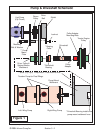
Figure 18
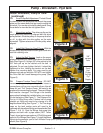
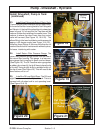
Tank Return
Filter
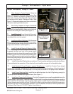
Install Driveshaft, Pump & Tank:
(continued)
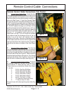
23. Install Hose Fittings into Return Filter in Tank.
There is a return filter in the top of the RH side of tank.
In the end of the filter housing install a Tee Fitting with
an Elbow in it, the tee fitting should point outward as
seen in figure 19. In the end of the Tee there will be
reducer to allow the installing of a smaller hose. This
reducer is where the return hose from the control
valve will connect (See Figure 18, 19 & 25). The
elbow fitting in the tee should be turned downward at
approx a 45 degree angle (see Figure 19 & 25) .
Installing these fittings in this way will allow the oil
cooler to be slid out for maintenance without hydrau-
lic hoses interfering with cooler.
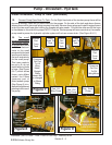
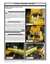
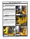
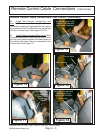
24. Install Return Filter Pressure Gauge. The
return filter pressure gauge screws into the side of
the return filter housing. This gauge is a low pres-
sure gauge that is marked in green and red areas.
(See Figure 19). The Oil Pressure return gauge has
a rubbery tip on top of it, the tip till have to have the tip
of it cutoff. Using a utility knife (or suitable knife) cut
the tip off now (See Figure 20). This will need to be
done before unit is run.
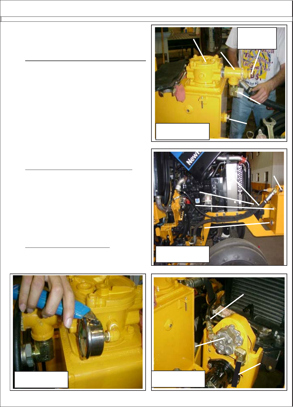
25. Install the Oil Level Sight Glass. The Oil Level
sight Glass screws into the Hydraulic tank. This is to
covered with oil when tank is a at operating level.
(See Figure 18 & 19)
Elbow
Fitting
Oil Level
Sight Glass
Pipe
Tee
Reducer
Fittting
Figure 20
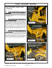
Figure 21
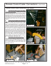
To Control Valve, Pressure
Line ("P" Port on Valve)
Tank
Suction
Line
Cyl. Control
valve Supply
Pump
Return Hose
from 4 Spool
Control valve
Port Marked "T"
Return Hose
from Wing
Motors
Return
Pressure
Gauge
Oil Level
Sight Glass
Oil Temperature
Gauge
Figure 19