


Installation - 3
41
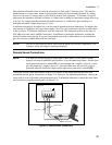
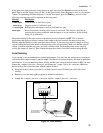
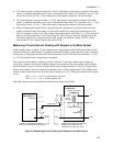
♦ You cannot measure voltages greater than +25 Vdc with respect to the negative terminal of the main
output. A situation where this could occur is illustrated by R1 in figure 3-8, which has only a 12 Vdc
drop across it but is 36 Vdc + Vlead with respect to the negative terminal of the main output.
♦ You cannot measure voltages less than −4.5 Vdc with respect to the negative terminal of the main
output. A situation where this could occur is illustrated by R6 in figure 3-8, which has only a −2 Vdc
drop across it but is −6 Vdc + Vlead with respect to the negative terminal of the main output.
♦ When calculating the common mode voltage between the point that you wish to measure and the
negative terminal of the main output, you must also include any voltage drop in the negative load
lead. For example, in figure 3-8, if the voltage drop in the negative load lead is 2 V, you would not be
able to correctly measure the 12 Vdc drop across R2. This is because when the voltage drop in the
load lead is added to the voltage drops across R2 and R3, the resultant voltage is 26 Vdc, which
exceeds the +25 Vdc common mode rating of the DVM.
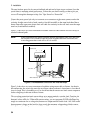
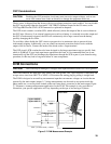
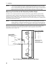
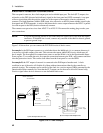
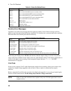
Measuring Circuits that are Floating with Respect to the Main Output
In the example shown in figure 3-9, the common mode voltage between the DVM inputs and the minus
terminal of the main output (output 1) includes an undefined floating voltage that may result in incorrect
readings due to clipping by the internal DVM measurement circuits. This will occur when the −4.5 Vdc
to + 25 Vdc common mode voltage range is exceeded.
The solution to this problem would be to provide a known or controlled common mode voltage by
connecting a jumper wire from the floating voltage to be measured to the main output. In this example,
the main output is set to 5V, the ac voltage to be measured is approximately 6 Vac (±8.5 Vpeak), and a
jumper wire connects one side of the bias transformer to the + main output terminal. This stabilizes the
common mode voltage and offsets it by the output voltage value (5 V). The peak common mode voltage
is now:
+8.5V + 5 V = +13.5 V on the positive side, and
−8.5V + 5 V = −3.5 V on the negative side;
with both voltages now being within the common mode range of the DVM.
A
g
ilent 66309D
A
g
ilent 66311D
OUTPUT 1
+
−
DVM INPUT
6 V Bias
Transformer
AC
ACC
+ 5 V
6 Vac;
8.5 Vpk
winding capacitance
winding capacitance
GNDGND
Undefined float voltage with respect to
GND due to capacitive currents.
Could be tens of volts ac or more.
Typically, low voltage with respect to
GND due to internal bypass capacitors.
GND
TO
DVM
j
umper wire
stray
capacitance
Figure 3-9. Measuring Circuits Floating with Respect to the Main Output