


Installation - 3
37
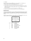
If the open sense lead protection circuit detects an open sense lead, the Prot annunciator on the front
panel turns on and the output turns off. Bit 5 in the Questionable Status Registers is also set (see chapter
7 under "Programming the Status Registers"). On the front panel, press the Prot key, and one of the
following error messages will be reported on the front panel:
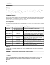
Message Description
+ sense open
Positive sense or load lead is open
- sense open
Negative sense or load lead is open
+/- sense open
Both positive and negative sense or load leads are open
sense open
Incorrect resistance reading on the sense or load leads. This may be caused by an
external power source paralleled with the output, or in rare instances, by the voltage
being out of calibration.
The default setting for the open sense lead protection circuit is disabled or OFF. This is because
applications that apply an external voltage to the output or that use external disconnect relays may
interfere with the operation of the open sense detect circuit. If you are using external voltages or relays,
you can enable the open sense detect at the beginning of the test procedure. Make sure that the external
voltage is disabled and that any relays are in the closed position. Perform the remote sense check by
cycling the output off, then on. Then disable the open sense detect circuit and continue using the unit.
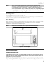
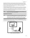
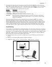
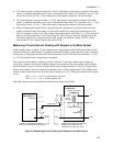
Local Sensing
Local sensing is not recommended for optimal performance. You must use the remote sense connections
on both the main output (output 1) and on output 2 for the unit to operate properly and meet its published
specifications. If you are not using remote sensing and the open sense protection feature is ON, you must
jumper the + output 1 pin to its + sense pin, and jumper the - output 1 pin to its - sense pin. Otherwise,
the unit will go into a protected state with the output disabled.
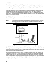
♦ Keep load leads as short as possible. Load leads cannot exceed 18 inches (per side) when local
sensing.
♦ Bundle or twist the leads tightly together to minimize inductance.
♦ Jumper the + output 1 pin to its + sense pin, and the - output 1 pin to its - sense pin.
LOAD
OUTPUT 1/OUTPUT 2
CONNECTOR
+
_
-S - + +S
TWIST LEADS
WIRE RESISTANCE
EACH LEAD MUST
BE LESS THAN 20
INCHES IN LENGTH
JUMPER
Figure 3-6. Local Sensing