


3 - Installation
34
The sense leads are part of the dc source’s feedback path and must be kept at a low resistance (less than
several ohms) to maintain optimal performance. Connect the sense leads carefully so that they do not
become open-circuited. If the sense leads are left unconnected or become open during operation, the dc
source will not regulate the output voltage. See "Open Sense Lead Protection".
Connect the remote sense leads only to the remote sense connections at the output connector and at the
location on the test fixture where you want to sense the output voltage. There must be not be any
continuity from the sense leads to earth ground or from the sense leads to the output leads other than at
the test fixture. The open sense detect circuit will check for continuity in the sense leads when the output
turned on (from disabled to enabled).
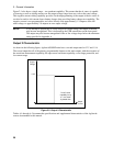
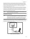
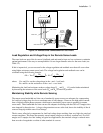
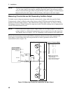
Figure 3-3 shows how to connect remote sense leads and load leads when external disconnect relays are
included in the load path.
NOTE: In this arrangement, the output of the unit should be programmed OFF before the relays
are switched. This is because if the load leads are opened before the sense leads, the
overvoltage protection circuit will trip if it is enabled.
LOAD
OUTPUT 1/OUTPUT 2
CONNECTOR
+
_
-S - + +S
TWIST LEADS
WIRE RESISTANCE
TWIST PAIR
DISCONNECT RELAYS
Figure 3-3. Remote Sense Connections with External Relays
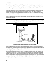
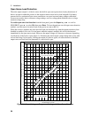
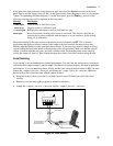
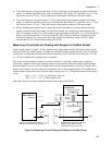
Figure 3-4 shows how to connect remote sense leads when using a removable test fixture. Note that in
this configuration, the wires in the part of the test fixture where the phone is located must be less than 20
inches in length. This is for stability as well as for the fact that the remote sense leads cannot compensate
for the voltage drop in this part of the test fixture.
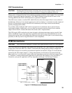
The overvoltage protection circuit senses voltage at the output terminals, not at the load. Therefore, due
to the load lead voltage drop, the voltage measured by the OVP circuit can be significantly higher than
the actual voltage at the load. When using remote sensing, you must program the OVP trip voltage high
enough to compensate for the voltage drop between the output terminals and the load. Also, if the sum of
the programmed voltage and the load-lead drop exceeds the maximum voltage rating of the dc source,
this may also trip the OV protection circuit. Refer to OVP considerations for more information.