


1 - Quick Reference
16
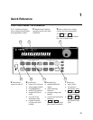
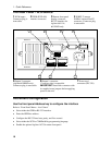
The Rear Panel - At a Glance
1 DVM inputs.
Connector plug is
removable.
2 GPIB (IEEE-488)
interface connector.
3 Remote front panel
display connector.
RS-232 interface for
Agilent 66111A,
66311B/D only.
4 INH/FLT (remote
INHibit / internal FauLT)
connector. Connector plug
is removable.
WARNING:
NO OPERATOR SERVICEABLE PARTS REFER SERVICING TO SERVICE TRAINED
WARNING:
FOR CONTINUED FIRE PROTECTION, USE SPECIFIED LINE
-+
+S
INH FLT
+-+
2 3 4
5 6
1
7
-S
OUTPUT 2
0 - 12V / 0 - 1.5A
OUTPUT 1
0 - 15V / 0 - 3A
-S
+S
+-
!
DVM
+-
5 Output 2 connector
(Agilent 66309B/D only).
Connector plug is removable.
6 Output 1 connector.
Connector plug is removable.
IMPORTANT: Install this connector with
its supplied sense jumpers before applying
power to the unit.
7 Power cord
connector (IEC 320)
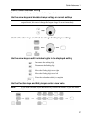
Instrument Configuration
Use the front panel Address key to configure the interface
Refer to “Front Panel Menus - At a Glance”
♦ Select either the GPIB or RS-232 interface.
♦ Enter the GPIB bus address.
♦ Configure the RS-232 baud rate, parity, and flow control.
♦ Select either the SCPI or COMPatibility programming language.
♦ Enable the optional Agilent 14575A remote front panel.