


3 - Installation
32
Output Connections
Turn the unit off before connecting any wires.
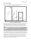
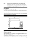
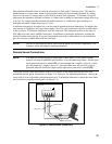
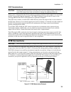
Output 1
The main output connector (output 1) has a termination for the + and − output, the + and − sense
terminals, and an earth ground terminal. The 5-pin connector is removable and accepts wires sizes from
AWG 22 to AWG 12. Disconnect the mating plug from the unit by pulling it straight back.
IMPORTANT: You must connect the sense terminals on Output 1 for the unit to operate properly. Refer
to the section on "Open Sense Lead Protection" in this chapter. Install the connector plug
with its supplied sense jumpers before applying power to the unit.
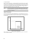
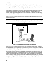
Output 2
Agilent 66309B/D units have a second output connector (output 2). It has the same configuration as the
main output connector. It has a termination for the + and − output, the + and − sense terminals, and an
earth ground terminal. The 5-pin connector is removable and accepts wires sizes from AWG 22 to AWG
12. Disconnect the mating plug from the unit by pulling it straight back. You must connect the sense
terminals on Output 2 for the unit to meet its published specifications.
Current Ratings
Fire Hazard To satisfy safety requirements, load wires must be large enough not to overheat when
carrying the maximum short-circuit current of the dc source.
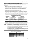
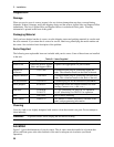
The following table lists the characteristics of AWG (American Wire Gage) copper wire.
Table 3-2. Ampacity and Resistance of Stranded Copper Conductors
AWG No. Maximum Ampacity (in
free air)
Resistance (at 20 deg. C)
Ω/m Ω/ft
24 3.52 0.0843 0.0257
22 5.0 0.0531 0.0162
20 8.33 0.0331 0.0101
18 15.4 0.0210 0.00639
16 19.4 0.0132 0.00402
14 31.2 0.0083 0.00252
12 40 0.0052 0.00159
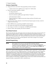
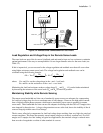
Voltage Drops and Lead Resistance
To optimize the performance and transient response in your test system, please observe the following
guidelines:
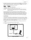
♦ Twist the load leads together and keep them short. The shorter the leads, the better the performance.
♦ When remote sensing, twist the sense leads together but do not bundle them in with the load leads.
♦ For best performance, keep the total cable length to the load to 20 ft or less when remote sensing.
(Note that the unit has been tested with cable lengths of up to 40 feet.)
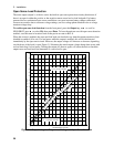
The load wires must also be of a diameter large enough to avoid excessive voltage drops due to the
impedance of the wires. In general, if the wires are heavy enough to carry the maximum short circuit
current without overheating, excessive voltage drops will not be a problem.