


8
Before installing
attachment, place
tractor on a firm
and level surface.
Place the PTO in
the disengaged
(OFF) position, set
the parking brake,
shut engine off and
remove key to prevent
unintended starting.
4
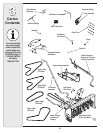
Assembly
Model Series
600-649 &
All 800 series.
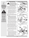
WARNING
WARNING: Before installing attach-
ment, place tractor on a firm and level
surface. Place the PTO in the disen-
gaged (OFF) position, set the parking
brake, shut engine off and remove key
to prevent unintended starting.
NOTE: References to LEFT and RIGHT indicate the left
and right sides of the tractor when facing forward in the
operator’s position. Reference to the FRONT indicates
the grille end; to the REAR the drawbar end.
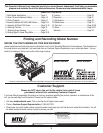
IMPORTANT: You must first figure out which model of
rider you are attaching this snow thrower to. Refer to
Determine Your Model of Rider on page 3 of this manual
to determine what model rider you are attempting to
install this attachment to. Then proceed to the applicable
instructions for your model of rider.
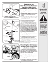
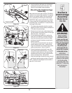
Your tractor’s cutting deck, PTO belt and front deck
stabilizer bracket must be removed prior to mounting
the snow thrower attachment. Refer to your tractor’s
Operator’s Manual for detailed instructions. If your
tractor is equipped with any front-end accessory (i.e.
front bumper kit), it must also be removed.
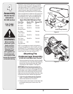
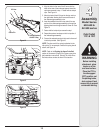
Mounting the
Idler Pulley and Pin
(Manual PTO Tractors equipped with
a 38- or 42-inch deck ONLY)
Frame Mount Dual Idler Style 2004 & Prior
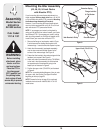
NOTE: If you engage your tractor’s cutting deck by
using your left hand to pivot a lever forward, your tractor
has a Manual PTO. If you engage your tractor’s cutting
deck by pulling outward on a small knob located on the
tractor’s dash, your tractor has an Electric PTO.
The idler pulley and pin (packaged separately, refer to
pages 6-7) must be installed to the PTO engagement
plate of all manual PTO tractors with a dual-belt drive
38- or 42-inch cutting deck. If applicable, proceed as
follows. Otherwise, proceed to Mounting the Under-
carriage Assembly.
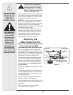
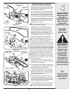
Locate the PTO engagement plate beneath your tractor.
See Figure 4.
Note the location of the weld pin on the rear portion of
the PTO engagement plate. This pin is where the deck
brake cable attaches, when operating the tractor with
the cutting deck mounted.
Remove the hair pin clip from the idler pulley and pin
(packaged separately). Refer to pages 6-7.
Position the idler pulley and pin onto the weld pin of the
PTO engagement plate and secure with the hairpin clip
just removed.
NOTE: This Idler pulley must be removed when
remounting the tractor’s cutting deck.
Figure 4
PTO Engagement Plate
Weld Pin Tractor Frame