


18
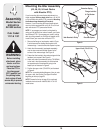
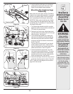
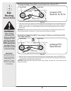
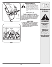
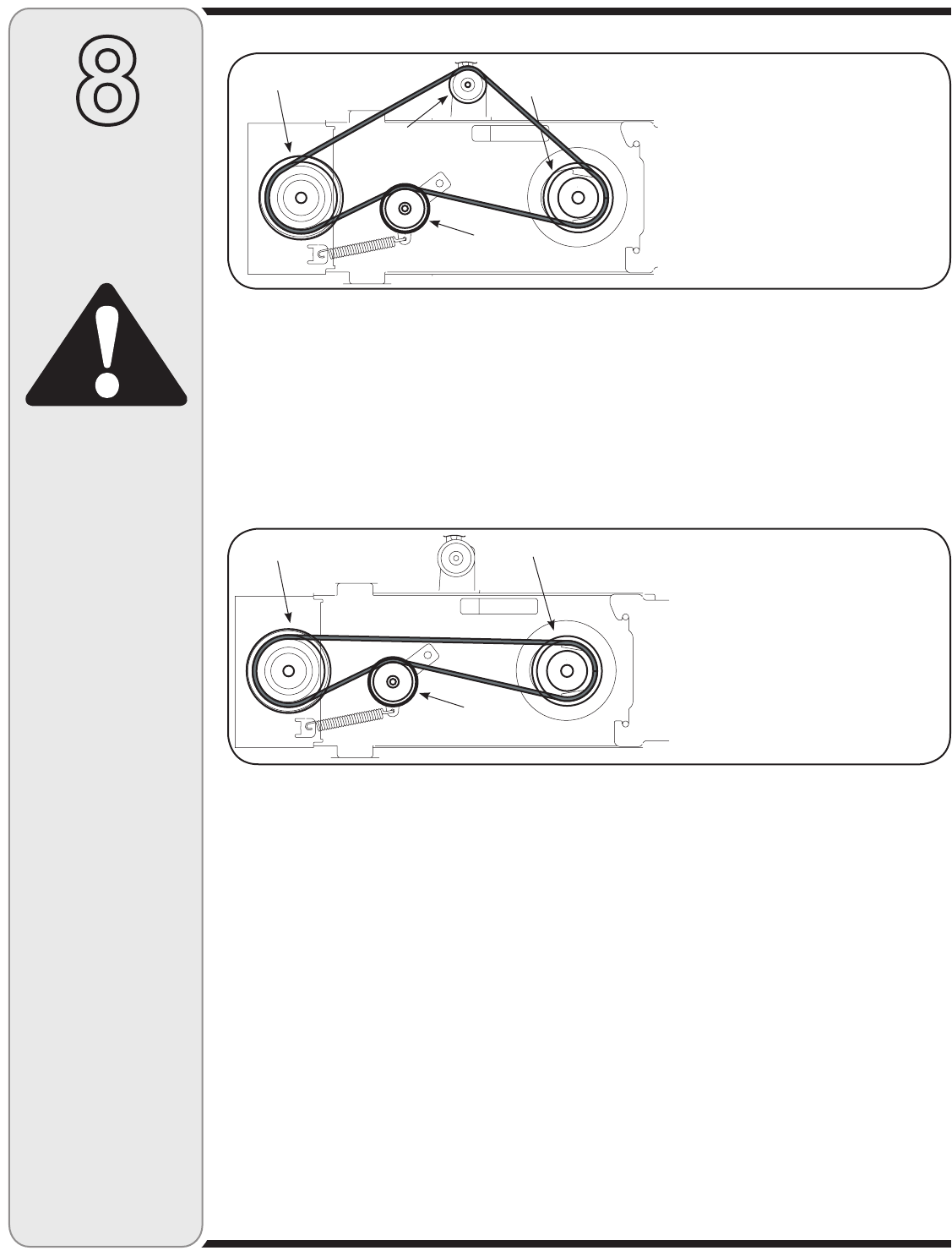
Figure 29
1. Attach and route the upper drive belt around the spindle pulley and idler pulley found on the undercarriage, the
electric PTO clutch and the PTO idler pulley as illustrated in Figure 29. Make sure that the belt is routed to the
INSIDE of the belt keeper on the undercarriage idler pulley and the remaining keeper pins found around the
spindle pulley.
IMPORTANT: Make certain that the flat side of the belt is facing outward as it sits against both the electric PTO
clutch and spindle pulley. This allows the “V” side of the belt to ride snugly in both pulleys.
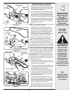
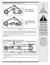
Routing the Upper Drive Belt (Tractors Models with an Electric PTO)
All electric PTO
Decks 42, 46, 50, 54
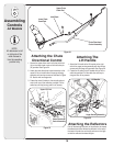
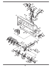
Figure 30
1. Attach and route the upper drive belt around the engine pulley and spindle pulley, routed to the INSIDE of the
PTO idler pulley on the undercarriage. Make sure the belt is routed inside of the belt keeper pins found around
the spindle pulley and engine pulley. See Figure 30.
IMPORTANT: Make certain that the flat side of the belt is facing outward. This allows the “V” side of the belt to ride
snugly in both pulleys.
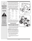
Routing the Upper Drive Belt (Tractor Models 700 Series; and 600 Series 2005 &
newer cable drive PTO)
All Manual PTO
Decks 38 & 42
Spindle Pulley Engine Pulley
Spindle Pulley
Engine Pulley
PTO Idler Pulley
Idler Pulley
PTO Idler Pulley
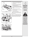
Belt
Routing
Various Models
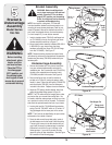
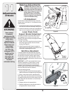
8
Before installing
attachment, place
tractor on a firm and
level surface. Place
the PTO in the disen-
gaged (OFF) position,
set the parking brake,
shut engine off and
remove key to prevent
unintended starting.
WARNING
IMPORTANT:
Make certain that the
flat side of the belt is
facing outward. This
allows the “V” side of
the belt to ride snugly
in both pulleys.