


16
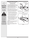
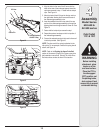
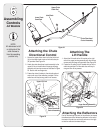
Attaching the Chute
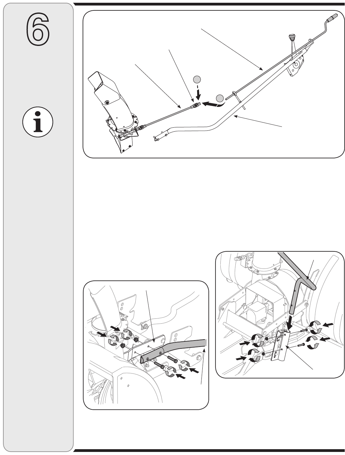
Directional Control
1. Secure the upper chute crank rod to the joint block
(A) on the lower chute crank rod with the cotter pin
(B) provided. See Figure 24.
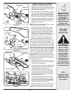
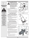
2. Attach the chute directional control assembly to the
upper lift link on the left side of the auger housing
assembly with two hex screws as illustrated in Figure
25. Secure with two flange nuts.
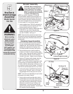
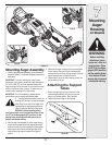
3. Fasten the chute tilt cables to the chute directional
control with two of the cable ties provided. Pull the
cable ties until they’re snug and trim off excess.
6
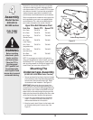
Assembling
Controls
All Models
NOTE:
All references to left
or right side of the
snow thrower is
from the operating
position only.
Attaching The
Lift Handle
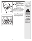
1. Attach the lift handle to the lift bracket on the right
side of the auger housing assembly with the two hex
screws and two flange nuts provided. See Figure 26.
2. Fasten the lift cable to the lift handle with two of the
cable ties provided. Pull the cable ties until they’re
snug and trim off any excess.
A
B
Figure 24
Upper Chute
Crank Rod
Lower Chute
Crank Rod
Joint Block
Chute Directional
Control Assembly
Figure 25
Figure 26
Chute Directional
Control Assembly
Upper Lift Link
Lift Handle
Auger Housing Assembly
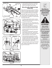
Attaching the Reflectors
Peel off the backing from each of the reflectors to expose
the adhesive surface. Adhere the reflectors to the rear of
the tractor’s fender (one on the left and one on the right)
so that the reflectors simulate taillights.