


14
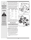
Bracket Assembly
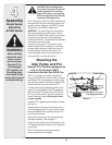
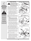
WARNING: Before installing attach-
ment, place tractor on a firm and level
surface. Place the PTO in the disen-
gaged (OFF) position, set the parking
brake, shut engine off and remove key
to prevent unintended starting.
NOTE: Your tractor’s cutting deck, PTO belt and
front deck stabilizer bracket must be removed prior to
mounting the snow thrower attachment. Refer to your
tractor’s Operator’s Manual for detailed instructions. If
your tractor is equipped with any front-end accessory
(i.e. front bumper kit), it must also be removed.
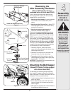
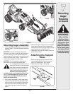
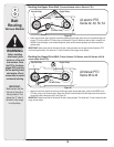
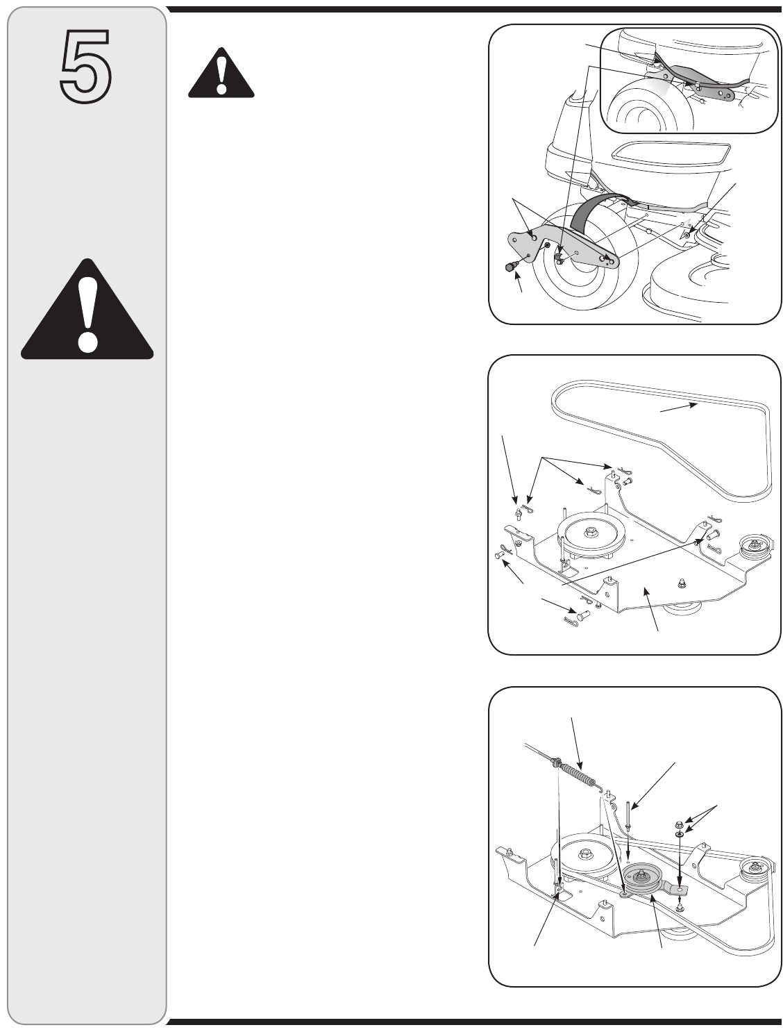
1. Install a shoulder screw (738-0143) and flange lock
nut (712-04065) in the top front hole of each snow
thrower assembly bracket as in Figure 17.
2. Mount snow thrower assembly brackets (683-04214
& 683-04215) to your tractor using the loose
hardware included (Hex Screw 710-0514 & Flange
Lock Nut 712-04065). See Figure 17.
NOTE: Remove the wiring harness from tractor frame
(left side only) and mount on the outside of the assembly
bracket using the clamp (726-0354) included with your
hardware pack.
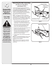
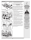
Undercarriage Assembly
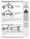
1. Remove the threaded pin, click pins and clevis pins
from your undercarriage assembly and retain for
installation later. Also, remove the v-belt (754-0371A),
this belt will be replaced later with another v-belt
(754-0498) included in this carton. See Figure 18.
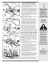
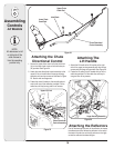
2. Remove the flange lock nut and flat washer as
pointed out in Figure 19, leaving the spacer under-
neath it in place. Mount the idler pulley (756-0627D)
and idler bracket (783-1291) from the loose parts
included in this carton. Replace the nut and washer.
3. Attach the PTO cable to the idler bracket, then fit the
cable into the slotted fitting as seen in Figure 19.
NOTE: The PTO cable should be hanging down under
you tractor after you removed the mowing deck. You
will need to slide the undercarriage unit under your trac-
tor in position for which it will be mounted. The slanted
side should be pointed towards the front of your tractor.
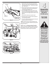
4. Locate v-belt part No. 754-0498 and the extension
spring (Part No. 732-04237, which is .50” wide x 12”
long) packaged with the loose parts in this carton.
NOTE: The V-belt can be identified by the part number
embossed on the outside of the belt.
5. Route the belt around the spindle pulley, inside of
the belt keepers and to the inside of the idler pulley.
The spring will connect to the Idler bracket but you
may install this once the undercarriage is mounted.
Otherwise it could fall off or get in the way in the
following steps. If you wish to connect this later,
retain the spring for later installation. See the Figure
20 illustration on the following page.
Before installing
attachment, place
tractor on a firm
and level surface.
Place the PTO in
the disengaged
(OFF) position, set
the parking brake,
shut engine off and
remove key to prevent
unintended starting.
Figure 17
Figure 18
Figure 19
5
WARNING
Undercarriage Assembly
Clevis Pins
Flange Lock
Nut & Washer
Idler Pulley &
Idler Bracket
PTO Cable
Threaded Pin
V-Belt
Bracket &
Undercarriage
Assembly
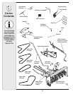
Model Series
700-799
Belt Keeper Pin
Shoulder
Screw
Flange
Lock
Nuts
Hex Screws
Slotted
Fitting
Wiring Harness
Clamp
NOTE: Left
side view