


12
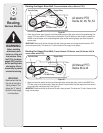
Because this snow thrower attachment is compatible
with several model lawn tractors and garden tractors
with either an electric PTO or a manual PTO, four upper
drive belts are included. If you have had any problems
locating the proper upper belts for installation in the
previous steps, use the table below for quick reference.
Refer to the table below to determine which upper drive
belt is applicable to your tractor; non-applicable belts
can be discarded. The v-belt can be identified by the
part number embossed on the outside of the belt.
Upper Drive Belt Reference Chart
Deck Size Electric PTO Manual PTO
54-in. Deck 754-0371A N/A
50-in. Deck 754-0371A 754-0481
46-in. Deck 754-0371A 754-0490
(Garden Tractor)
46-in. Deck 754-0371A 754-0481
(Lawn Tractor)
42-in. Deck 754-0371A 754-0481
(single-belt drive)
42-in. Deck 754-0371A 754-0435
(dual-belt drive)
38-in Deck N/A 754-0435
(dual-belt drive)
NOTE: If you engage your tractor’s cutting deck by
using your left hand to pivot a lever forward, your tractor
has a Manual PTO. If you engage your tractor’s cutting
deck by pulling outward on a small knob located on the
tractor’s dash, your tractor has an Electric PTO.
Mounting The
Undercarriage Assembly
(All 600-649 & 800 Model Series Tractors)
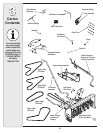
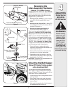
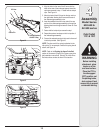
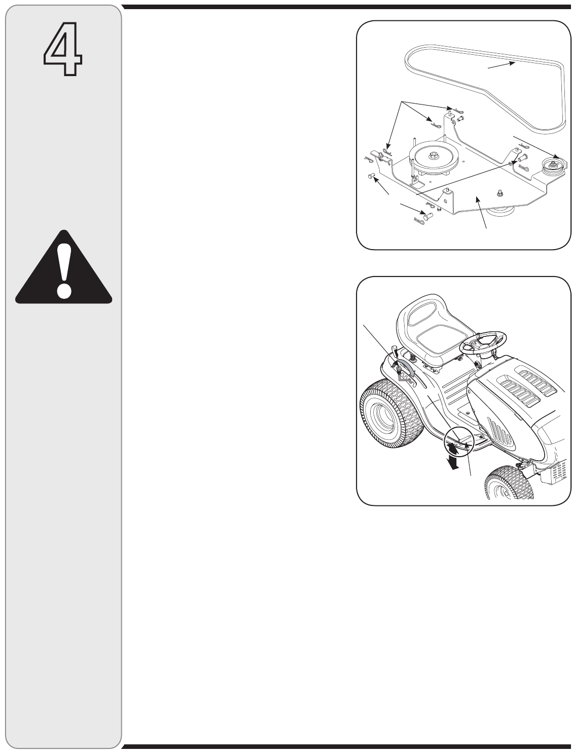
1. Remove and retain the four hairpin clips from the weld
pins found the top side of the undercarriage assembly,
and also the 4 clevis pins with hairpin clips. Retain
this hardware for later installation. See Figure 12
.
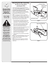
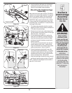
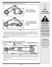
IMPORTANT: Make certain the correct upper drive
belt is installed on the undercarriage assembly prior to
proceeding with mounting the undercarriage. Make sure
that the upper v-belt is routed to the INSIDE of the belt
keeper found on the undercarriage idler pulley and the
keeper pins found around the spindle pulley. Also, make
certain that the flat side of the belt is facing outward.
2. Position the undercarriage assembly beneath the
tractor. For manual PTO units, hook up the PTO
cable as described earlier in this section
.
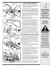
3. Move the tractor’s deck lift lever into the lowest notch
on the fender allowing the lift arms to drop. See
Figure 13.
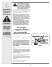
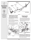
Before installing
attachment, place
tractor on a firm
and level surface.
Place the PTO in
the disengaged
(OFF) position, set
the parking brake,
shut engine off and
remove key to prevent
unintended starting.
4
Assembly
Model Series
600-649 &
All 800 series
Cub Cadet
11C & 13C
WARNING
Figure 12
Figure 13
Deck Lift
Lever
Lift Arm
Undercarriage Assembly
Click Pins
Clevis Pins
V-Belt
Belt Keeper