


13
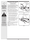
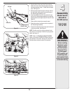
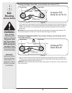
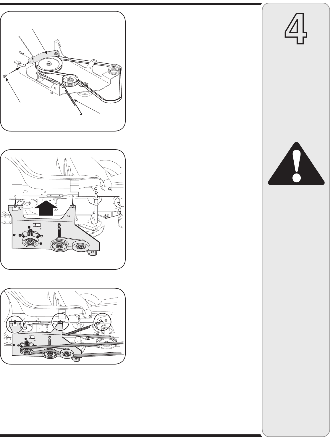
4. Align the holes in the rear of the lift arms with the
holes in the rear of the undercarriage and insert the
clevis pins removed in step 1. Fasten with the hairpin
clips. See Figure 14.
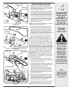
5. Move the tractor’s deck lift lever into the top notch on
the right fender allowing the lift arms and the rear of
the undercarriage assembly to rise.
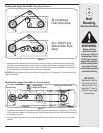
6. Insert the weldpins found on the top side of the rear
portion of the undercarriage assembly up through the
aligning holes found along the tractor’s frame rail. See
Figure 15.
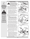
7. Fasten with the hairpin clips removed in step 1.
8. Repeat the previous two steps on the front portion of
the undercarriage assembly.
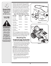
9. Connect the extension spring to the tractor’s frame rail
in the hole provided. See Figure 16.
NOTE: The other end of the spring is attached to the
idler pulley. For an example of where this spring should
attach, see Figure 14.
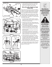
NOTE: Refer to the Routing the Upper Drive Belt
section of this manual (Page 18) for proper upper drive
belt installation instructions. Routing The Lower Drive
Belt instructions can also be found in that section.
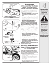
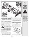
Before installing
attachment, place
tractor on a firm
and level surface.
Place the PTO in
the disengaged
(OFF) position, set
the parking brake,
shut engine off and
remove key to prevent
unintended starting.
4
Assembly
Model Series
600-649 &
All 800 series
Cub Cadet
11C & 13C
WARNING
Figure 14
Lift Arm
Clevis Pin
Figure 15
Figure 16
Spring Attached
to Idler Pulley