


15
5
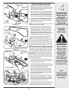
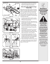
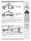
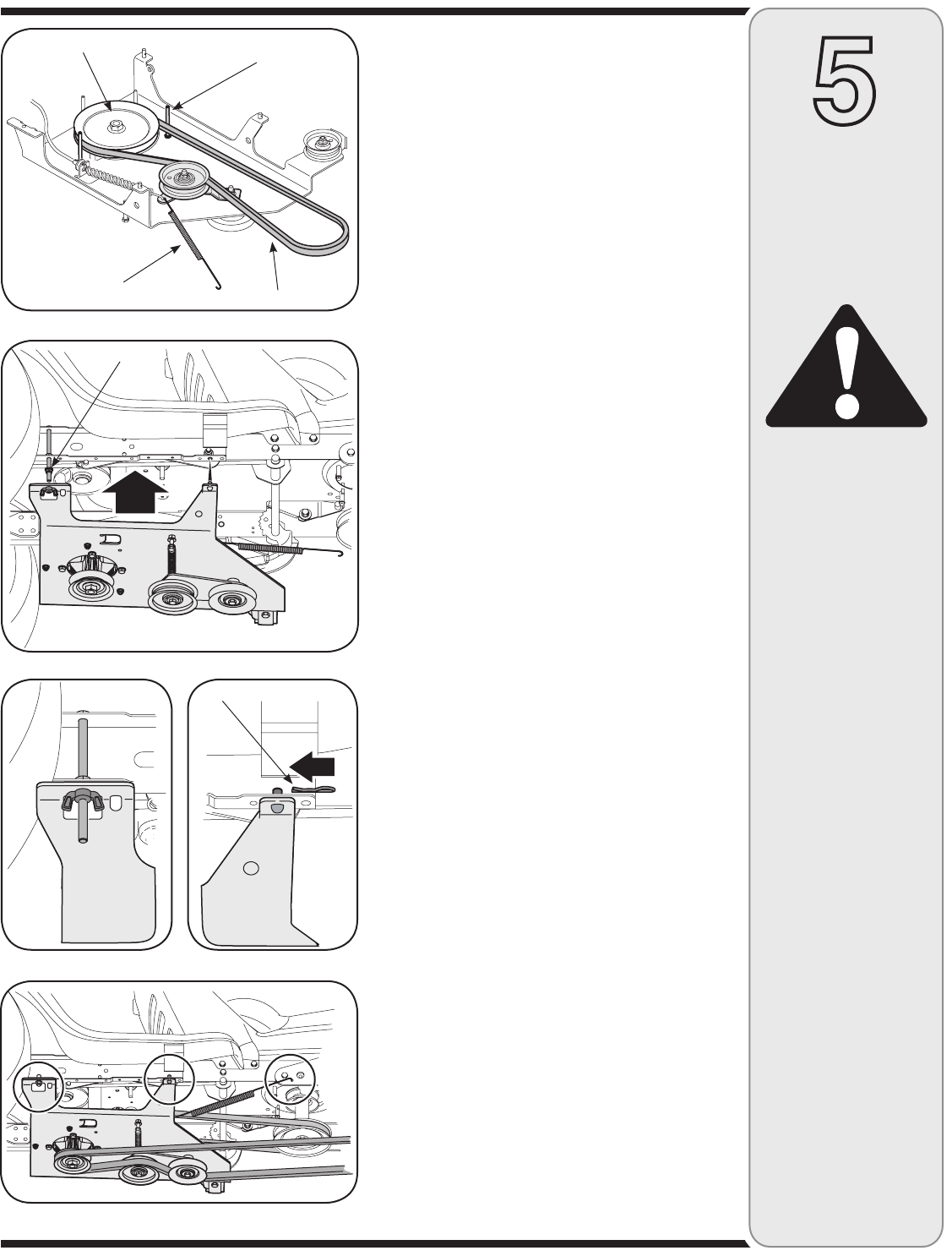
Figure 20
Before installing
attachment, place
tractor on a firm and
level surface. Place the
PTO in the disengaged
(OFF) position, set
the parking brake,
shut engine off and
remove key to prevent
unintended starting.
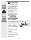
IMPORTANT:
Make certain that the flat
side of the belt is facing
outward as it sits against
both the idler pulley
and spindle pulley. This
allows the “V” side of the
belt to ride snugly in
both pulleys.
6. Install the additional belt keeper pin and hardware
included with the loose parts in this carton. See
Figure 19 for belt keeper location placement.
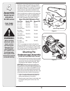
Mounting the Undercarriage
Assembly
Make certain the correct upper drive belt (754-0498) is
installed on the undercarriage assembly. If the appropri-
ate belt is not installed, replace it with the correct belt
prior to proceeding with mounting the undercarriage.
IMPORTANT: Make certain that the flat side of the belt
is facing outward as it sits against both the idler pulley
and spindle pulley. This allows the “V” side of the belt to
ride snugly in both pulleys.
1. The undercarriage assembly should be in position
beneath the tractor, since you already connected the
PTO cable in the previous steps.
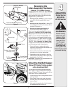
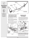
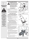
2. Remove the nut from the rear undercarriage mount-
ing stud located on the tractors frame rail on the right
side of the tractor. See Figure 21.
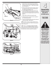
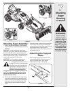
3. Lift the undercarriage assembly up, inserting the
weld pins on the assembly up through the aligning
holes found along the tractor’s frame rails. Fasten
with hairpin clips and flat washers removed earlier.
See B in Figure 22.
The rear hole on the right side will fit over the stud
already installed on your tractor. Fasten with the
wing nut (included with your hardware pack) and flat
washer removed earlier. See A in Figure 22.
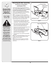
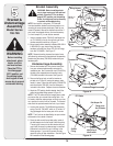
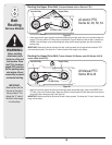
4. Connect the extension spring found in your units
loose parts that was mentioned earlier. This spring
connects to the idler bracket on the undercarriage
assemble and the hole on the rear right-hand snow
thrower mounting bracket. See Figure 23.
5. Attach the lower auger drive belt by routing it around
and through the pulley system as seen in Figure 23.
NOTE: Proper belt routing diagrams can be found on
page 18-19 of this manual.
WARNING
Figure 21
Figure 22
Bracket &
Undercarriage
Assembly
Model Series
700-799
V-Belt
Belt Keeper
Pin
Extension Spring
Spindle Pulley
Figure 23
A B
Remove Nut
Hairpin Clip