


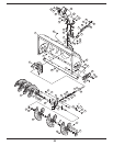

17
7
Mounting
Auger
Housing
All Models
Before installing
attachment, place
tractor on a firm and
level surface. Place
the PTO in the disen-
gaged (OFF) position,
set the parking brake,
shut engine off and
remove key to prevent
unintended starting.
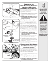
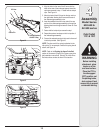
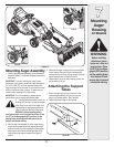
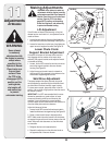
Mounting Auger Assembly
1. Position the auger housing assembly in front of the tractor
as seen in Figure 27. Lay the belt and support tubes out as
seen above.
IMPORTANT: If you are installing this snow thrower
attachment on any mower model with a letter designation
(i.e. 60R or 80R, 80T, etc.) then the heat shield on the
auger housing must be removed. Do not remove this heat
shield on any other model of mower. To determine your
model number, see page 2-3 of this manual.
IMPORTANT: It will be necessary to have a second
person assist you to complete the following steps.
2. Carefully move the tractor forward (by
pushing, NOT driving it) so that the support
tubes found on the rear of the auger hous
-
ing assembly are positioned between the
tractor’s front tires. Set the parking brake.
WARNING: Before installing attach-
ment, place tractor on a firm and level surface. Place
the PTO in the disengaged (OFF) position, set the
parking brake, shut engine off and remove key to
prevent unintended starting.
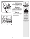
3. With the help of an assistant, lift up the auger housing
up and move the attachment back aligning the hooks
found on the rear of the lift assembly over the shoulder
bolts found on both the left and the right sides of the
tractor’s front pivot support brackets. See Figure 27
Inset A.
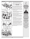
4. Maneuver the auger housing until the mounting holes
lineup. Insert a clevis pin from your hardware pack
and secure with a click pin, into the tractor’s front pivot
support brackets seen in Figure 27 Inset B.
5. Repeat Step 4 on the left side, inserting a clevis pin
secured with a click pin.
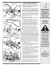
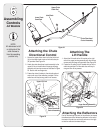
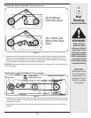
Attaching the Support
Tubes
1. Secure the right support tube to the front of the
undercarriage assembly with the clevis pin and
hairpin clip removed earlier. See Figure 28.
2. Repeat the previous step on the left side.
Figure 27
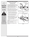
WARNING
Figure 28
Inset B
Inset A