


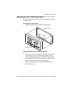

Installing the Link 1000
16
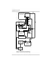
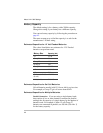
Connecting Terminal Block Wires to Shunt and Battery
To connect the terminal block wires:
1. Connect the black DC power wire (terminal 1) to the
large bolt on the load side of the shunt. This wire should
be on the top of the stack of large cables on the load side
of the shunt. Do not connect this wire to the small
screw terminal with the green shunt sense lead.
2. Connect the green lead (terminal 2) to the small screw on
the load side of the shunt. This wire must be one half of
the twisted pair made up of wires 2 and 3. Do not connect
any other wires to this screw.
3. Connect the orange lead (terminal 3) to the small screw
on the battery side of the shunt. This wire must be one
half of the twisted pair made up of wires 2 and 3. Do not
connect any other wires to this screw.
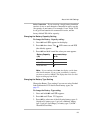
4. Connect the blue voltage sense lead (terminal 4) to a 2
amp fuse holder located within 7 in. (18 cm) of the
battery. Connect the other side of the fuse holder to the
positive battery terminal. Do not install the fuse yet.
5. Connect the red power wire (terminal 5) to a 2 amp fuse
holder located within 7 in. (18 cm) of the battery.
Connect the other side of the fuse holder to the positive
battery terminal. Do not install the fuse yet.
6. If you are going to monitor a starting battery, connect the
violet second battery voltage sense lead (terminal 6) to a
2 amp fuse holder located within 7 in. (18 cm) of the
second (starting) battery. Connect the other side of the
fuse holder to the positive battery terminal of the starting
battery. Do not install the fuse yet.
Note: If you are going to monitor the starting battery,
you must enable Function F11 during setup. See
page 33.