


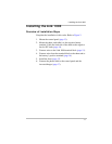

Installing the Link 1000
15
Wiring the Terminal Block
Prepare for wiring by following these guidelines:
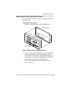
• Pull the wires and the phone cable through the opening in
the mounting plate (unless you are running them down
from the bottom of the mounting plate).
• Prepare the wires by giving each:
• A clean cut
•A clean strip
• A tightly twisted end
• Loosen the terminal block screws, pry the wire clamps
open with a paper clip, and insert the wires using needle-
nose pliers.
• Tighten the screws firmly, but do not overtighten.
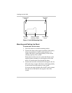
To wire the terminal block:
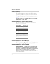
• Insert the wires in the terminal block following the
sequence shown below.
Note: Terminal 1 is next to the phone cable jack.
Terminal
Wire Color and Function
1Black. Control panel negative to the large bolt on the
load side of the shunt.
2 Green. Sense lead to the load side of the shunt.
3Orange. Sense lead to the battery side of the shunt.
4Blue. Voltage sense lead to the positive battery
terminal.
5Red. Power lead to the positive battery terminal.
6 Violet. Voltage sense lead to the positive battery
terminal. Connect this lead if you are monitoring the
voltage of a second (starting) battery.
7 Not used
8 Not used