


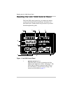

Reading the Link 1000 Control Panel
5
2, 3 Numeric display and display units.
You can choose from four display units depending on the
type of information you want to see:
• Volts
•Amps
• Ah (Amp-hours)
• Time Remaining
The procedure for changing display units is given on
page 36 along with an explanation of each display unit.
Note
: The numeric display also shows Error Codes. If
an error occurs, the display alternates between the
monitoring function you have selected and the Error
Code. For details about Error Codes, see page 48.
4
SEL and SET buttons
SET lets you access Setup mode and advanced
functions. Once you are in Setup mode, you press
SEL to choose a function or a setting. Procedures for
changing values are given in Chapter 3.
5 CHARGE/PWR SHARE button and LED
Lets you start a charge cycle (see page 40) or change the
Power Share mode setting (see page 27).
6
INVERT/IDLE MODE button and LED
Lets you activate the invert function (see page 38) or
change the Idle mode setting (see page 28).
7
RESET, DATA, LOCK, FUNC LEDs
•
RESET: When it is on, this LED indicates that you are
resetting Ah (Amp-hours) to zero or that you are
returning all settings to the factory defaults. (See
page 21.)
•
DATA: Indicates that you are looking at historical
information about your batteries. (See “Interpreting
Battery History” on page 46.)
•
LOCK: Indicates you are choosing the setting that
prevents people from inadvertently changing your
setup values. (See page 21.)
•
FUNC: Indicates you are accessing the advanced
functions. (See “Advanced Function Values” on
page 29.)