


44 Assembly
MAN0943 (07/12/2011)
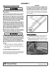
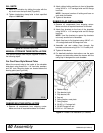
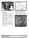
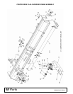
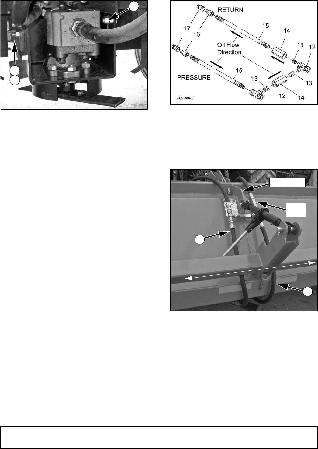
Figure 53. Motor Assembly Installed
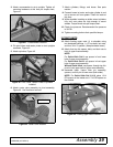
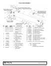
Assembly Hoses
1. Attach male quick coupler (17) and adapter (16) to
the end of hose (15). Attach tee (12) to the
opposite end of hose.
2. Attach male quick coupler (17) and adapter (16) to
the end of second hose (15). Attach check valve
(14), nipple (13) and tee (12) to the opposite end of
hose.
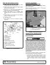
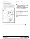
NOTE: Make sure flow indicator arrow on the side
of the check valve (14) is pointing in the correct
direction. See Figure 54
3. Install check valve (14) and two nipples (13)
between the two tees (12).
NOTE: Make sure flow indicator arrow on the side
of the check valve (14) is pointing in the correct
direction.
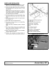
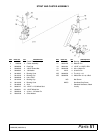
4. Place hose assembly around center plate of
shredder and drape quick couplers over the front of
the shredder. See Figure 54 and Figure 55.
5. Make sure hose with check valve is on the right
side of the center plate.
Figure 54. Hose Assembly
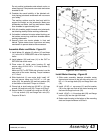
6. Route hose (11) from the IN side of the motor
between shredder and rockshaft and attach it to
tee (12) on the left side of the center plate.
7. Route hose (11) from the OUT side of the motor
between shredder and rockshaft and attach it to
tee (12) on the right side of the center plate.
Figure 55. Hose Routing
31
30
29
DP1
Check
Valve
11
Center Plate
RETURN
PRESSURE
L
e
f
t
R
ig
h
t
DP2
11
IN
OUT