


32 Service & Maintenance
MAN0943 (07/12/2011)
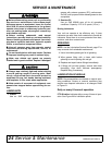
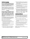
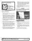
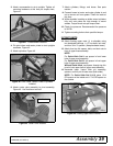
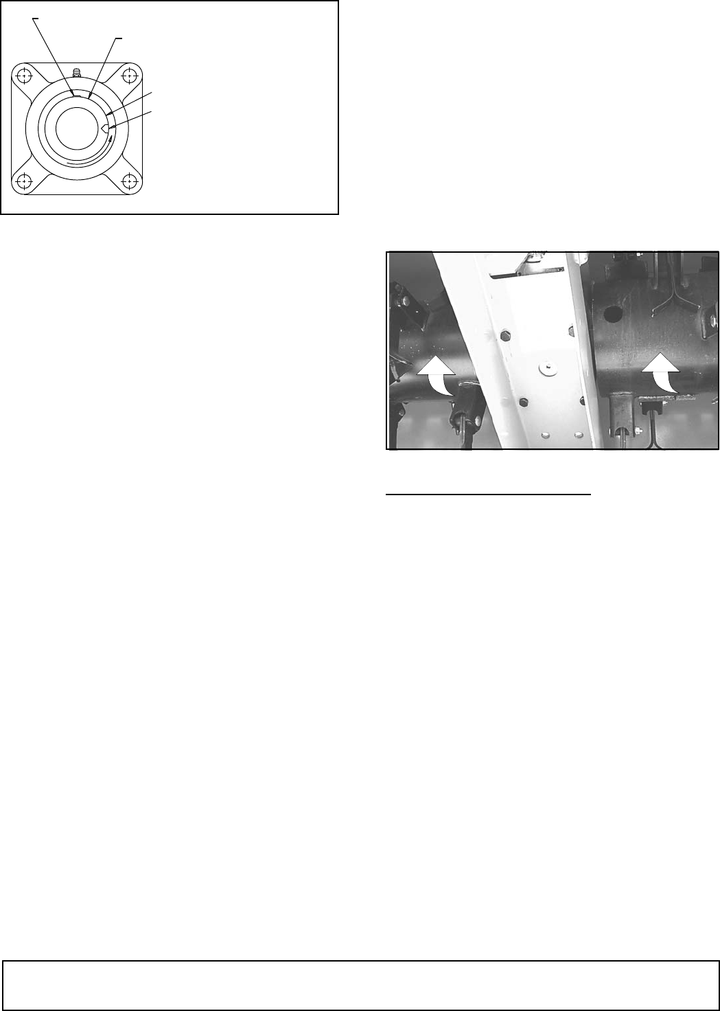
Figure 35. Locking Collar
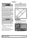
Replacing Components
1. Place new stud bolts into gearbox using Loctite
®
No. 271 or equivalent.
2. Remount gearbox. The gearbox oil dipstick should
protrude out the top panel of the shredder for
checking and servicing. Reinstall the nuts and lock
washers securing the top of the gearbox to the
shredder gearbox mount plate and torque to
specifications in Bolt Torque Chart, page 59.
3. Remount the crossmember securing the bottom of
the gearbox and torque to specifications in Bolt
Torque Chart, page 59.
4. Install drive couplings and reapply new grease
around entire O-ring and gear teeth surfaces.
5. Install rotors (flail tubes) in the opposite fashion as
removal. Position rotors with each end supported
by a crane or hoist so that it is aligned with the gear
coupling and gearbox output shaft center lines.
The bearing (stub shaft) end of the rotor will
protrude out of the hole in the end sheet.
6. With gentle care not to damage gear coupler teeth
or O-ring, provide pressure to align gear teeth and
slide the rotor back into its original position.
NOTE: When re-installing rotors, the gear coupling
grease fitting will need to be temporarily removed
to allow for air to purge from the coupler assembly
during installation. After successful installation,
reinstall grease fitting and re-service.
7. Reinstall bearing plate assembly and bolts, and
apply appropriate torque.
8. Reinstall bearing locking collar and tighten (see
Figure 35).
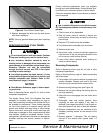
NOTICE
■ If removing rotor drive coupling, use Loctite No.
271 or equivalent and special high collar lock
washers to keep bolts from loosening.
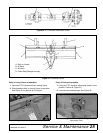
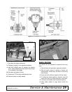
Figure 36. Rotor Direction of Rotation
REPLACING STUB SHAFT
1. Remove rotor (see Servicing Rotors (Flail Tubes),
page 31).
2. Remove three 1/2 x 2-1/2 hex bolts in taper lock
hub and re-install bolts in three threaded holes
(see Figure 37).
3. Tighten bolts evenly to release taper lock hub from
stub shaft. NOTE: You may have to give a sharp
blow directly to each bolt head to help the hub
disengage.
4. Unscrew stub shaft from the rotor tube.
5. Install new stub shaft, reversing Steps 1-3.
MAN0506003
P E E R
F S 2 1 1
LOCKING COLLAR
LOCKING COLLAR SET SCREW
SHAFT
FOR REMOVAL: TAP
WITH A HAMMER AND
PUNCH AFTER LOOSENING
SET SCREW.
FOR INSTALLATION:
REVERSE PROCEDURE
DP15