


Service & Maintenance 31
MAN0943 (07/12/2011)
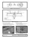
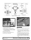
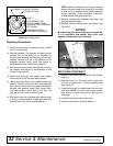
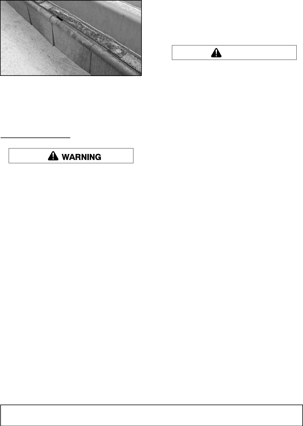
Figure 34. Front Rubber Shield Flaps
4. Replace damaged flap with new flap and secure
with correct hardware.
NOTE: Use only genuine Woods parts when replacing
flaps.
SERVICING ROTORS (FLAIL TUBES)
Do not handle knives with bare hands. Careless
or improper handling may result in serious injury.
■ Any excessive vibration caused by worn or
missing knives or damaged drive components can
cause damage to the shredder and personal injury.
Excessive vibration can also be transmitted
through the hitch mounts and PTO to the tractor
resulting in tractor damage.
■ Once field operation has been started, it is the
responsibility of the owner/operator to monitor and
maintain acceptable rotor balance. Refer to Bal-
ance Statement, page 5, for details.
NOTICE
■ Read Balance Statement, page 5, before replac-
ing any knives.
Refer to Replacing Knives, page 30, for knife or knife
component replacement.
The Woods Center Drive Flail Shredder has been
designed for durability when shredding any type of
crop. Some operating conditions will shorten the life of
the shredder or components. These include operating
too low to the ground or in frequent contact with the
ground, and contact with large rocks or other foreign
objects. Over time, some types of soils and crops can
cause wear or damage to rotor components and affect
rotor balance, leading to increased vibration. Contin-
ued operation with excessive vibration can damage the
shredder, requiring rotor service, removal, or replace-
ment.
Factory balanced replacement rotors are available
through your local Woods dealer. Contact Woods Tech-
nical Service for re-balance options or further details.
Follow the procedure below if rotor removal or replace-
ment is required.
Use a suitable lifting device of sufficient capac-
ity. Use adequate personnel to handle heavy com-
ponents.
1. Clear the area of any bystanders.
2. Shut off tractor, place all controls in neutral, set
parking brake, remove key, and wait for all moving
parts to stop.
3. Remove PTO driveline from the shredder.
4. Fully disconnect the shredder from the tractor.
5. Remove wheel arms.
6. Use a hoist, crane, or frame of sufficient capacity to
raise the front of the unit and allow the back of the
unit to rest on a solid surface (blocks).
7. Leave lifting device attached while working on
rotors to prevent tipping.
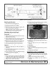
Removing Components
Refer to Replacing knives, page 30, for knife or knife
component replacement.
Refer to Servicing Rotors, page 31, before proceeding
with these steps.
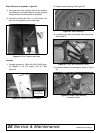
1. Follow steps in the previous section to prepare and
position shredder. Support each end of the rotor
(flail tube) to be removed with a crane or hoist.
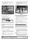
2. Remove bearing locking collar (see Figure 35).
3. Remove the six bolts holding the bearing plate to
the body assembly.
4. Slide rotor out to disengage from the center drive
coupling.
5. Thoroughly clean and inspect gearbox drive
couplings for wear and replace if any wear is
detected. Also inspect the rubber O-ring for wear or
tears and replace if any wear or tears are detected.
6. Remove crossmember from the underside of the
shredder, providing access for the removal of the
gearbox.
7. Remove gearbox, if damaged. This will require
removal of the second rotor (repeat steps 1-5
above).
DP117
CAUTION