


16 Operation
MAN0943 (07/12/2011)
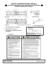
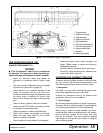
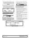
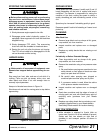
Figure 2. Tractor Front Weight
3. 3-Point Hitch
The 3-point hitch models require that the tractor be
equipped with a Category II or Category III 3-point
hitch. If the hitch can be converted from one to the
other, use a Category III to provide a wider stance and
more stability.
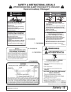
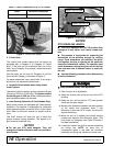
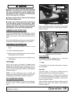
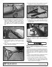
Use the upper top link hole for Category III and the
lower hole for Category II as shown in Figure 3.
For easier attachment, use a quick hitch. If not using a
quick hitch, use optional hitch extension.
4. Hydraulic Requirements when Using Center
Cutter Options
The tractor hydraulic system must be capable of 8 gpm
(30 lpm) at 1500 psi (10,335 kPa). The system cannot
exceed 28 gpm or 3000 psi. Either closed-centered or
open-centered systems can be used.
5. Load Sensing Hydraulics (3-Point Models Only)
Many newer tractors are equipped with “load sensing”
hydraulics. The operator is responsible for setting the
tractor hydraulic system to provide “float” on the 3-point
hitch. Refer to the tractor manual for specific instruc-
tions.
The “float” feature will allow the unit to follow the
ground contours during operation. This applies to 3-
point mounted machines only.
NOTICE
■ Do not use PTO shaft adapters. They will
change the drawbar dimension and can cause driv-
eline failures.
Figure 3. 3-Point Hitch Attachment
NOTICE
PTO DRIVELINE LENGTH
■ The unit is equipped with a PTO driveline long
enough to fit any tractor and 3-point linkage sys-
tem.
■ The operator is responsible for measuring the
dimensions of the driveline through its working
range. These dimensions will indicate if the drive-
line requires shorting to operate on the particular
tractor/unit attachment system. The operator must
check dimensions before using the unit for the first
time and each time a different tractor is used with
the unit.
■ Use the following procedure when determining
driveline dimension:
Keep bystanders away from equipment.
1. Clear the area of all bystanders.
2. Attach the 3-point hitch to the unit but not the PTO
driveline.
3. Raise the unit until the tractor PTO and gearbox
shafts are the same height.
4. Measure the dimension between the shaft grooves
on the tractor and implement ends. If this
dimension is less than 34.81 inches, the shaft will
require shortening.
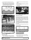
5. Move the unit to its highest and lowest working
position and measure this dimension again. [The
unit’s shaft can telescope (see Figure 5) before it
has been shortened.]
6. If required, shorten the shaft to prevent bottoming
out during use. NOTE: An extra inch of
compression space in the shaft can eliminate
bottoming out during use. Measure to make sure.
Table 1: Tractor Horsepower (6-8) vs. Unit Width
Width Minimum Horsepower
30’ 180
DP10
Top Link Assembly
Upper Top Link Hole
Lower Top Link Pin
Lower 3-Point Pin
DP11